Chapter 10
SITEWORKS
Introduction
Terminology
Standards
Plant and Equipment
Introduction
Site work involves the preparation of a site for building and incorporates everything from land surveying to demolitions, excavating and site establishment. Site work includes a wide range of pre-construction activities encompassing soil investigation, preparing the site for construction, shoring, earthworks and levelling, installing various types of piping – water distribution, drainage and sewage pipes, and erecting site facilities like huts, and fences.
Terminology
AASHTO
(The American Association of State Highway and Transportation Officials) – A soil classification system of natural material before stabilisation.
Bank cube
The volume of undisturbed ground before it is excavated (in situ in cubic metres).
Clay
A cohesive material made up of microscopic particles (less than 0.002mm) and vary widely in properties; some have more moisture movement than others.
Cofferdam
A temporary watertight enclosure around an area of water bearing soil or an area of water from which the water is removed (via pumping) allowing construction to commence in a water free area.
Compaction
The act of compressing soil to increase its density.
Demolish
Pull or knock down an existing structure (building).
Dewatering
Pumping subsurface water from an excavation to maintain dry and stable working conditions.
Excavate
Dig out or extract material from the ground
Gravel
Hard rock material in particles larger than 6.4mm in size but smaller than 76mm.
Groundwater
Water that exists below the surface of the earth and passes through the subsoil.
Metamorphic rock
Rock formed by the action of pressure or heat on sedimentary soil or rock.
Rock
A solid mineral material found naturally in large masses.
Sand
Fine rock particles from 0.05mm in size to less than 6.4mm in size
Shale
Clays that have been subjected to high pressures, causing them to become relatively hard.
Site (building)
An area where a structure is being built or repaired.
Site plan
A drawing of a construction site, showing the proposed locations of buildings, site contours, and other improvements.
Survey
Examine and record the feature of an area of land or examine and report on the condition of a building.
Surveyor
A professional person who examines the condition of a piece of land or a building
Topography
The arrangement of the natural and artificial physical features of an area (such as mountains, levels, trees, etc.).
SG Diagram
A drawing compiled by a registered land surveyor indicating positions and lengths of site boundaries and coordinates and angles to determine its position and size relative to other land. The drawing will also indicate servitudes. This drawing is registered with the surveyor general (SG) for any future reference – See Figure 10.1 for an example.
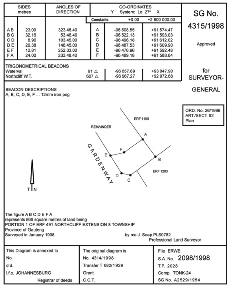
Figure 10.1 – Example of a Surveyor General Diagram
Standards
Extracts from SANS 10400 Part F: Site operations
SANS 10400 establishes general requirements for satisfying the National Building Regulations issued in terms of the National Building Regulations and Building Standards Act, 1977 (Act No. 103 of 1977), and some of these requirements that are deemed to satisfy the following parts of such Regulations of Part F: Site Operations are highlighted below:
F2 Damage to Local Authority’s Property
- Where any work connected with the demolition or erection of any building may, in the opinion of the local authority, cause or have any detrimental effect on the strength, standard, safety, quality or position of any property belonging to or vested in such local authority, the local authority may require the owner of such building to pay to the local authority such deposit or give such security, as it may require to cover the costs of the repair of any damage which may be caused by such work.
- In the event of damage to the local authority’s property being so caused the local authority may appropriate the amount of the deposit or security contemplated in subregulation (1) towards the costs of repairing such damage: Provided that if the amount of the deposit or security exceeds such costs, the balance shall be refunded to the owner: Provided further that if such costs exceed the amount of the deposit or security, such owner shall be liable to the local authority for the deficit.
- Where any deposit contemplated in subregulation (1) has not been lodged with the local authority, the owner of such building shall pay the cost of such repair to the local authority on demand, failing which the local authority may recover such cost from the owner in a court of competent jurisdiction.
F3 Geotechnical Site and Environmental Conditions
- Where the local authority has reason to believe that a site upon which a building is to be erected
- (a) Is situated on contaminated land;
- (b) Is situated on potentially unstable land to the extent, insofar as risk can reasonably be foreseen,that ground movements caused by land-slip, slope-stability or subsidence may impair the stability of the building or part thereof or pose a threat to the safety of occupants; or
- (c) is underlain by subsoil’s which have the potential to cause foundation movements caused by swelling, consolidation, shrinkage or settlements and as a result may impair the stability of the building or part thereof; it shall on receipt of an application for the erection of the building inform the applicant accordingly.
- On receipt of any such notification or where the applicant is aware of such conditions or they are evident, such applicant shall appoint an approved competent person to undertake an appropriate geotechnical site investigation.
- Such approved competent person shall, as appropriate, determine in accordance with accepted principles, methods and technical considerations, as relevant:
- (a)Whether or not the erection of a building on the site under (1)(a) or (1)(b) above should be permitted ,and if so under what conditions, providing full details of the measures which need to be effected to fulfil such conditions and (b)The magnitude of any potential total and differential movements to which the building or part thereof may be subjected to, and shall report to the owner and the local authority such findings.
- Geotechnical investigations conducted in accordance with the requirements of SANS 10400-B in the case of dolomite lands and SANS 10400-H in the case of foundations for buildings shall in terms of F3 (2) be deemed to be appropriate investigations.
- The measures contemplated in sub-regulations (3)(a) and (b) shall be applied in the erection of the building and the site works.
F4 Preparation of Site
- Before any foundation is laid the area to be covered by any building shall be properly cleared of vegetable matter, tree stumps, timber and other cellulose material, debris or refuse and any material contaminated with faecal matter.
- Where any site upon which any building is to be erected is waterlogged, seasonally waterlogged or saturated, or where any building is to be so situated that water will drain naturally towards it, drainage shall be provided to direct such water away from such site or building to a stormwater drain or to dispose of it in some other safe approved manner.
F5 Soil Poisoning
- Buildings shall, where so required by the local authority or in areas of high termite infestation, be protected from subterranean termite activity.
- The requirements of subregulation (1) shall be deemed to be satisfied where the means of termite protection complies with SANS 10400-F.
F6 Control of Unreasonable Levels of Dust and Noise
- The owner of any land on which excavation work is in progress or on which any building is being erected or demolished shall take precautions in the working area and on surrounding roads and footways to limit to a reasonable level the amount of dust arising from the work or surroundings thereof.
- (a) No person shall during the course of any building, demolition or excavation work use any machine, machinery, engine, apparatus, tool or contrivance, which in the opinion of the local authority may unreasonably disturb or interfere with the amenity of the neighbourhood:
- (i) On a public holiday or Sunday
- (ii) Before 06:00 or after 17:00 on any Saturday
- (iii) Before 06:00 or after 18:00 on any day other than those days contemplated in subparagraphs (i) and (ii)
- (b) The prohibition in paragraph (a) shall not apply in any circumstances in which the use of such machine, machinery, engine, apparatus, tool or contrivance –
- (i) Is urgently necessary in order to preserve the life, safety or health of any person
- (ii) Is urgently necessary to preserve property;
- (iii) Has been authorized by the local authority; or
- (iv) is necessary for the execution of work
- Any owner or person who contravenes a provision of this regulation shall be guilty of an offence.
F8 Waste Material on Site
- Where in the opinion of the local authority, excessive rubble, rubbish, other debris or combustible waste material is allowed to accumulate on a site before or during building operations, it may, by written notice, order the owner of such site to have such rubble, rubbish, other debris or combustible waste material removed within the period specified in such notice.
- Any owner who fails to comply with such notice shall be guilty of an offence and the local authority may remove the said rubble, rubbish, other debris or combustible waste material from such site and may recover the costs of such removal from the owner.
F9 Cleaning of Site
- Any owner or person erecting or demolishing any building shall remove any surplus material and matter arising from such erection or demolition from the site and from any other land or public street or public place affected by such material or matter during or after the completion of such erection or demolition, failing which the local authority may, by written notice, order the owner of such building to have such surplus material and matter removed within a period specified in such notice.
- Any owner or person who fails to comply with a provision of subregulation (1) or a notice served on him in terms thereof, shall be guilty of an offence.
F10 Builder’s Sheds
- Any owner or person carrying out or performing work in connection with the erection or the demolition of any building, may erect on the site of such work such temporary builder’s sheds as may be necessary.
- The construction and location of such sheds shall be to the satisfaction of the local authority and such sheds shall be maintained in good order.
- Subject to the provisions of subregulation (6) such sheds shall only be used for a purpose connected with the carrying out or the performance of the work referred to in subregulation (1).
- Where such sheds are not constructed, located or maintained in terms of this regulation, the local authority may serve a notice on such owner or person to move, reconstruct or repair or improve the condition of such sheds within a time specified in such notice, or if use thereof is being made other than that permitted in terms of this regulation, to cease such unpermitted use.
- On completion or cessation of the work referred to in subregulation (1) or where such sheds are no longer necessary for the purpose for which they were erected, they shall be removed from the site by the owner.
- Security personnel employed in connection with a building which is being or which is to be erected or demolished may be accommodated in builder’s sheds, subject to such requirements and conditions as may be necessary for the safeguarding of public health and the health of such personnel and for avoiding nuisance or inconvenience to persons in the vicinity of such building.
- Any owner or person who fails to comply with any provision of this regulation or any notice served on him in terms thereof, shall be guilty of an offence.
F11 Sanitary Facilities
- No owner or person shall commence or continue the erection or demolition of any building unless approved sanitary facilities for all personnel employed on or in connection with such work have been provided or are available on the site or, with the permission of the local authority, at some other place: Provided that where such facilities have not been so provided the local authority may order the cessation of such work until the required facilities have been provided, and, should such order not be complied with, the local authority may install such facilities and recover the costs of such installation from the owner of the site.
- Any owner or person who contravenes any provision of this regulation, or fails to comply with an order served on him in terms thereof, shall be guilty of an offence.
- The requirements of subregulation (1) shall be deemed to be satisfied where the provision of sanitary facilities complies with SANS 10400-F.
Plant and Equipment
The activity of site work, usually involves the use of a large amount of construction plant and equipment (plant is the term typically used to refer to equipment and machinery used on a site). On small residential projects one normally relies on available manpower to perform general site work; however, modern construction equipment is used on a regular basis on larger projects as it becomes more cost effective and less time consuming to use this type of plant and equipment, which can be categorised in three groups:
- Excavation plant
- Earth-moving plant
- Compaction plant
Earth-moving plant can often double up as excavation plant and vice versa; and is normally chosen based on the following factors:
- Site conditions
- The volume of work required
- The economies of scale – (What is the most cost effective machinery to be used that suits the activities involved)
The final choice of plant to be used or hired is usually left to the experience, availability, familiarity with a particular machine or brand, and the personal preference of the contracts manager or site agent(s). Most often, it is not viable for a contractor to own his own plant and for this reason a lot of this plant is hired (rented).
There are a myriad plant hire companies in South Africa that hire a wide range of plant from large excavating equipment to small tools; these companies can also offer guidance in determining what type of plant would best suit the application.
Excavation plant
Excavation plant includes the following types of machines:
- Skimmer
- Face shovel
- Backactor
- Dragline
- Multipurpose excavator
- Trencher
The most commonly used excavating machines on a building site are the excavator and TLB (Tractor Loader Backactor) as described below:
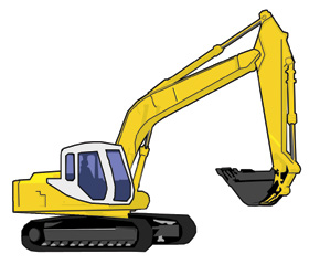
Excavator
A large machine with a digging bucket.
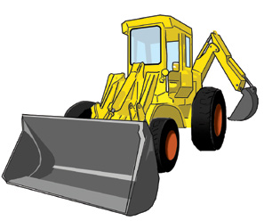
TLB
A combination of a loader with a bucket on an articulated arm at the front and an excavator (digger) on an articulated arm at the back.
Earth-moving plant
Earth-moving plant includes the following types of machines:
- Bulldozer
- Front-end loaders
- Scrapers
- Graders
The most commonly used earth-moving machines on a building site are the TLB (as described above), the bulldozer and front-end loader described below:
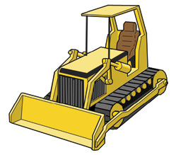
Bulldozer
These machines are primarily high-powered tractors on tracks, fitted with a broad curved upright blade in in the front for clearing ground and topsoil excavation.
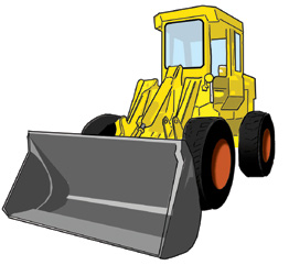
Front-end loader
Front end loaders are the most versatile machines available on a construction site. A front end loader is a wheel driven machine with a scoop or bucket on an articulated arm at the front for loading different types of materials. Bucket capacities also vary depending on the machine’s specification. They are often fitted with teeth instead of a straight cutting edge to enable excavating activities in harder soil – often referred to as ripping.
Compaction plant
Compaction plant is designed to compact filling like under surface beds and surface finishes like substrates for paving or premix for roads and parking areas. Civil works like roads use large compaction equipment specifically for this kind of work, whereas general building work uses smaller equipment. Besides compaction plant being divided into these two distinct groups, compaction plant can be further divided into the following categories:
- Static weight rollers
- Vibrating rollers
- Pneumatic rollers
- Vibrating plates
- Impact plates/rammers
The type of compaction obtained depends on the soil type, type of equipment being used and application. In small works it will generally be found that the use of hand compaction equipment such as tampers/stampers is used. This type of compaction is found to not provide a sufficiently uniform dense compaction and the use of light-powered compaction equipment is always recommended such as plate compactors, impact rammers or walk-behind vibrating rollers – as described below.
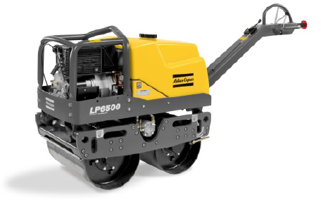
Mini-vibrating roller
Often referred to as a ‘Bomag’ are hand operated and used to compact walkways, parking areas, behind concrete retaining walls and the like.
Vibrating plate
A machine that is made up of a steel plate that is allowed to vibrate by means of a petrol motor referred to as a plate compactor; commonly used for compacting surface bed filling and the grouting to paving.

Impact rammer
Kinetic energy is utilised by raising a heavy weight and allowing it to fall on the surface being compacted; commonly referred to as a ‘Wacker’ and used in very tight areas like behind retaining walls or small pipe excavations.

Other construction plant
The plant described below is not necessarily used for site work activities; however, site location and the required services, for example water, need to be considered and provided for:
Mortar mixing
Mortar for the construction of small residential projects is normally mixed by hand. Suitable gauge boxes or other measuring equipment should be provided to ensure the correct proportioning of the constituent materials which is discussed in greater detail in the Superstructure section – Section 10. Hand mixing should always be done on a close-boarded mixing platform or prepared surface (pad) to prevent contamination of the mix by materials picked up off the surface. Where the scale of construction justifies it mechanical mixers can be used. Typical equipment used is a 300 litre drum-type cement mixer, powered by a small petrol or diesel engine. Depending on the size of the project, mixing plants should not be too large, so that it can be moved around the site to suit construction requirements.
Concrete mixing
Concrete for the construction of small residential projects is normally mixed by hand. Suitable gauge boxes or other measuring equipment should be provided to ensure the correct proportioning of the constituent materials which is discussed in greater detail in the Foundation section – Section 9. Hand mixing should always be done on a close-boarded mixing platform or prepared surface (pad) to prevent contamination of the mix by materials picked up off the surface. Where the scale of construction justifies it, the following types of concrete mixers can be used:
Free-fall mixers – e.g. tilting drum and reversing drum powered by a small petrol or diesel engine have blades that lift the concrete to the top of the drum and allow it to fall and so mix. These mixers are suitable for most normal concretes but cannot handle concretes of low workability, of lean mix proportions and concrete that is over-cohesive (very sticky).
Forced-action mixers – e.g. pan mixers powered by a small petrol or diesel engine have blades that shear the concrete. Pan mixers consist of either a stationary pan with rotating blades or a rotating pan and blades. This type of mixer can handle concrete of any workability especially the semi-dry concrete mixes required for structural components.
Again depending on the size of the project, mixing plants should not be too large, so that it can be moved around the site to suit construction requirements.
Transportation plant
The transportation discussed here is about the transportation on site and not the use of trucks in delivering materials or removing unwanted soil or rubble. Transportation of materials on site is an important element in the production process and the following forms of transportation need consideration in terms of site mobility and access.
Wheelbarrows – commonly used for transporting concrete, bricks and mortar from the stockpiles and batching plants respectively to the point of use.
Dumper – basically a mechanised wheelbarrow with a bigger load and is able to carry larger quantities.
Crane and skip – used for tall buildings and where access is limited; contractors often use a crane fitted with a special bucket (skip) to transport materials to the point of use on the site.
Scaffolds – Scaffolding requires consideration in terms of site layout and location for adequate mobility and access to allow for the offloading of materials at the point of use. Scaffolding is described in more detail in the Superstructure section.
Sundry builder’s tools – Normal builder’s tools, such as picks, spades, shovels, hammers, hosepipes, levels and the like will be required. Tools for each trade are covered in each section and then in more detail in the tool section – Section 23
The Building Site
Site assessment
Before any construction work can begin, the building site must be thoroughly analysed and understood to ensure an efficient construction process. The more common site assessment processes are described below.
Site surveying
Site surveying is a method of accurately determining points and lines of direction (bearings or co-ordinates) on the earth’s surface and preparing from them maps or plans. Boundaries, areas, elevations, construction lines, and geographical or artificial features are determined by the measurement of horizontal and vertical distances and angles and by computations based on geometry and trigonometry. The height of points in relation to a datum line (usually mean sea level) is measured with a levelling instrument consisting of a telescope fitted with a spirit level and usually mounted on a tripod. It is used in conjunction with a levelling rod placed at the point to be measured and sighted through the telescope. The transit is used to measure vertical and horizontal angles and may be used also for levelling; its chief elements are a telescope that can be rotated (transited) about a horizontal and about a vertical axis, spirit levels, and graduated circles supplemented by vernier (small movable graduated scale for obtaining fractional parts of subdivisions on a fixed main scale) scales.
Known also as a transit theodolite, or transit compass, the transit is a modification of the theodolite, an instrument that, in its original form, could not be rotated in a vertical axis. The stadia method of measuring distance, a rapid system useful in surveying inaccessible terrain and in checking more precise measurements, consists in observing through a telescope equipped with two horizontal cross hairs or wires (stadia hairs) the interval delimited by the hairs on a calibrated stadia rod; the interval depends on the distance between the rod and the telescope. Surveys based on photographs are especially useful in rugged or inaccessible country and for reconnaissance surveys for construction, mapping, or military purposes. In air photographs, errors resulting from tilt of the airplane or arising from distortion of ground relief may be corrected in part by checking against control points fixed by ground surveys and by taking overlapping photographs and matching and assembling the relatively undistorted central portions into a mosaic. These are usually examined stereoscopically (this is where two photographs of the same view, but taken at slightly different angles, are viewed together, creating an impression of depth). Maps or plans that represent the natural and artificial features of the earth’s surface, like hills and rivers, roads and houses and so on are commonly referred to as topographical maps or plans.
The Site plan
A site plan shows the placement of buildings, roads, and other improvements, including existing contours of the land and (if so required) the desired finished contours. Locations of water, sewerage and electrical connections are also shown. Other details, such as fences, swimming pools, retaining walls and the like are also located on the site plan.
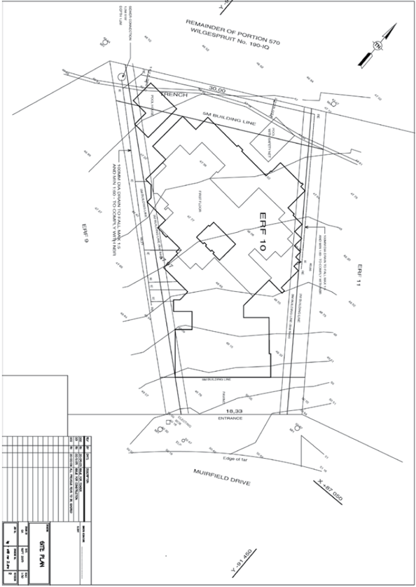
Example of a site plan
Environmental Assessment
The coordinated efforts, of building owners, architects, landscape architects, civil engineers, other professionals and construction companies are required to ensure that the structure being built will optimize site utilization, work well within existing natural systems, and minimize environmental damage. An Environmental Impact Assessment (EIA) of the building site could be called for by the local authority; which would have typically formed part of the plan approval phase. We highlight in table 10.1 below the Site Sensitivity levels covered in the National Building Regulations as described in SANS 10400: Part A.
Table 10.1.1 – Classification *
| Low Sensitivity site |
| A site that is neither identified as, nor exhibits, any evidence of environmental or heritage significance and does not require Environmental Impact Assessment (EIA), Heritage Impact Assessment (HIA) or Social Impact Assessment (SIA) studies to be undertaken before development. Low sensitivity sites are normally, but not exclusively, within already developed urban areas. |
| Medium Sensitivity site |
| A site which exhibits some evidence of environmental or heritage significance for which EIA, HIA or SIA studies are not required by the government agencies involved. |
| High Sensitivity site |
| PA site identified as of special environmental or heritage significance and which will require EIA, HIA or SIA studies to be undertaken to define the parameters for development, for example, declared protected areas and urban conservation areas. |
* The inherent importance of the site in environmental or heritage terms, as defined by the National Heritage Resources Act, 1999 (Act No. 25 of 1999), the National Environmental Management Act, 1998 (Act No. 107 of 1998), and the Local Government: Municipal Systems Act, 2000 (Act No. 32 of 2000).
In addition, to assess potential or existing environmental contamination, an environmental site assessment could also be required if the site is on reclaimed land, close to an industrial area or mine. The environmental site assessment looks for contamination to soil, subsurface materials, and the existence of hazardous substances.
Geotechnical Investigation and Soil Tests
A key factor in the building process is the evaluation of the geotechnical character of a site in the context of existing or proposed works or land usage and the determination of the characteristics of the soil upon which the structure is to be built. This may include one or more of the following factors:
- evaluation of the geology and hydrogeology of the site
- examination of existing geotechnical information pertaining to the site
- excavating or boring in soil or rock and the systematic description of the soil and rock profiles
- determining the depth of any fill that might be present
- in-situ assessment of geotechnical properties of materials
- recovery of samples of soil or rock for examination, identification, recording, testing or display
- testing of soil or rock samples to quantify properties relevant to the purpose of the investigation
- evaluation of geotechnical properties of tested soils
- reporting the results
The objectives of the geotechnical investigation and soil testing are to determine what construction methods need to be used. It is very common that soil tests are done for large projects and developments, but not as common in small residential housing projects. The consequences of not providing sufficient, accurate and reliable geotechnical information can have a huge effect on a project; possibly leading to delays and extra costs being incurred during construction. In addition, the structure could fail because of incorrect or insufficiently designed foundations. The cost of a good geotechnical investigation is very low in comparison to the total cost of the project. This geotechnical investigation requires the testing of site-soil samples in a laboratory or by means of a field test.
Field identification
Experienced geotechnical technicians and engineers can identify a soil by just looking at the physical characteristics of a soil. The most obvious is that of colour. Apart from colour, soil is identified in the field using the following characteristics.
Shaking test
Take a handful of wet soil and form a ball of about 25mm in diameter. The ball is placed in the open palm and shaken horizontally so it hits against the palm of the other hand. The appearance of a glossy surface caused by water constitutes a positive reaction. As the sample is further shaken, the ball stiffens as the water gloss disappears. The ball will finally crack or crumble. Very fine sands give the quickest reaction; inorganic silts give a moderately quick reaction; and clays give no reaction.
Compressibility
Take a handful of wet soil and shake it around in the palm of your hand. If there is water on your skin, the soil is defined as showing characteristics of compressibility. With the soil still in your palm, close your hand and squeeze the soil. When you open your hand, you will find that the soil remains in a lump but now appears stiff and crumbly. Very fine sands will crumble soon thereafter, while clays will remain stiff.
Toughness test – Plastic characteristics
A toughness test ascertains the consistency of a soil sample near the plastic limit. The test is to demonstrate the cohesive (ability to stick together) properties of clay. Take a soft lump of clay (roughly a 12mm cube) and roll it in your hand to form a long thread about 3mm in diameter. As you continue rolling, the thread becomes stiffer as the water evaporates – this is the plastic phase of soil. When the soil crumbles it has reached its plasticity and crumbles. Now shape the clay into a lump again and start to roll a new thread (note how difficult it has become since the first time); the tougher the thread is near the plastic limit and the stiffer the lump when it crumbles, the more colloidal clay there is in the soil. Weakness in the thread at the plastic limit and easy crumbling of the lump indicates the presence of either inorganic clay with low plasticity or organic clay.
Dry strength
The dry strength test begins by wetting a soil sample until its consistency approaches that of stiff putty and moulding it into a ball of approximately 25mm in your hand. Then place it in the sun and allow it to dry out for a few hours. Once dry hold the sample between your thumb and forefinger and apply pressure and note the pressure necessary for it to crumble. Repeat the process if necessary for different types of soils, taking careful note of the different pressures needed for each soil sample to crumble. This characteristic is known as the dry strength of the soil. If it does not break or crumble, the soil is highly plastic and characteristic of clays. If the sample breaks but is difficult to rub the crumbled sections to a powder when rubbed between the fingers, it has a medium plasticity. If the sample breaks easily into a powder it has low plasticity.
Colour Soils
These usually have a distinguishing colour; dark or black soil indicates the presence of organic matter in the soil, while lighter coloured soils indicate they are inorganic. Clay is whiteish to a light grey. Soils with iron-oxide particles give soil its reddish colour. While beach sand and sand dunes are clear or white.
Smell
Certain soils smell when disturbed and is usually distinctive when freshly disturbed, especially in organic soils, for example a compost layer; the more distinctive the smell the greater the presence of organic matter in the soil.
Feel / coarseness
The feel or touch of a soil can distinguish silts from clays and from sand. Take a handful of sand and rub it between your fingers – feel how coarse it is. By using other soil samples you can distinguish between the roughness and coarseness of each. Grab a lump of clay and you can immediately tell the difference. Sand is coarse; clay is smooth and greasy and can even be sticky.
Soil moisture content
The moisture content of soil plays an important part in determining the physical properties of the soil and is an important factor during soil compaction; the density will vary depending on the moisture content. Simply put – one can say that water acts as a lubricant in the soil and allows particles to move better over each other when compacted. A moisture content in optimal amounts enables soil to be compacted to its maximum density. This is called the optimum moisture content and is determined by laboratory testing of soil samples.
Another factor to consider when examining soil on site is its permeability. Permeability measures the ability of water to penetrate through the soil. Sand has a high permeability rating, while clays have a low permeability.
Soil Classification
Soils are classified by the sizes of their particles and their physical properties. Most soils are a mixture of the following five types of soils:
- Gravel – a hard rock material with particle sizes larger than 6.4mm in diameter but smaller than 76mm.
- Sand – consists of fine rock particles smaller than 6.4mm in diameter to 0.05mm.
- Silt – consists of fine sand particles smaller than 0.05mm and larger than 0.002mm..
- Clay – is a very cohesive material with microscopic particles less than 0.002mm..
- Organic matter – is partly decomposed animal and vegetable matter..
The process of classification is to place a soil sample in a group or class that can be internationally accepted and understood. Soil classification systems are based on particle sizes found in the soil mass and where the system recognises three main types of soil:
- Coarse grained* / cohesion-less soil, e.g. sand
- Fine grained/cohesive soil, e.g. clay
- Organic soil, e.g. peat
* Grained refers to the individual mineral properties in the soil.
- Coarse grained soils – the sieve analysis test is usually carried out on these soils. This is because the size of the particles and the proportions of the different sizes have an important effect on the behaviour of the soil. Coarse grained material does not necessarily mean large particles, umgeni sand or beach sand can also be considered as coarse grained material.
- Fine grained soil – the properties of fine grained soil are affected by the water content. The criteria for testing are that of consistency and plasticity. Consistency is the tendency of the particles to stick together, while plasticity is the ability of the soil to deform without rupture or breaking (see toughness test above)
- Organic soil – The properties of peat and other organic matter are insufficient in bearing strength they are extremely compressible and structures built over peat may settle by very large amounts over long periods of time.
Two of the most commonly used soil classification systems in South Africa are:
- Casagrande classification system
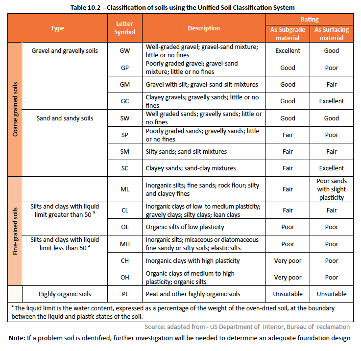
- Unified Soil Classification System (USCS)
The Unified Soil Classification System classifies soils according to the percentage of grain-size particles in each of the established soil grain sizes in the soil distribution index, the liquid limit, and the organic matter content. Soils are grouped in fifteen classes – eight of which are coarse grained soils; six are fine grained; and one class of highly organic soil. Soils on the borderline between two classes are given a dual classification, for example GP-GM.
There is a basic difference in behaviour between coarse granular soils and fine cohesive soils. The percentage of silt and clay size particles (or fines smaller than 0.06 mm) in a soil is important since, when this percentage is high, the soil will cease to behave as a granular soil. The critical magnitude of the fines content is expected to be in the range of 10–25%, and typically about 15%.
Soil Bearing Capacities
A field test can be conducted in determining the bearing capacity of an open foundation trench by taking a deformed reinforcing bar/rod of around 1m in length with a diameter of 16mm (minimum) and then try pushing this bar into the ground by hand (don’t use a hammer). If the bar can be pushed in easily for more than 300mm to 1000mm then the bearing capacity is inadequate. One can excavate further until a suitable stratum is found and the bar can no longer be pushed into the ground. For buildings not exceeding two storeys the local authority or building contractor would usually be able to assist with determining whether the soil in the area is capable of carrying these types of loads – For multi-storey buildings an engineer must always be consulted.
If the soil in the area of the building is uniform in composition and the foundation design is adequate, the building will remain stable. While some settlement may occur over time, it will remain uniform. If the soil composition varies and is not compensated for in foundation design, the building could experience differential settlement. In most cases where poor soil conditions are encountered it is necessary to test soil samples in a laboratory to determine the maximum allowable pressure that a soil can support.
Foundation design
Various types of foundations are used to accommodate different soil conditions and types. Foundation design is discussed in the Foundation Section – under the heading – Foundation types.
Site work activities
Erosion and Stormwater Control
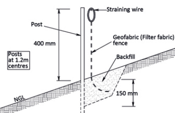
Throughout the construction process, potential stormwater, erosion and sedimentation problems must be controlled. These control measures prevent loss of soil by storm runoff and wind, which includes damage to neighbouring properties. Many local authorities may require that erosion and stormwater control measures be put in place before the actual building work commences. Sediment is soil that has eroded and is transported by either water or wind. Erosion describes the washing or wearing away of exposed soil through actions of wind and water, as well as equipment and foot traffic. A cost effective measure for preventing soil loss is by erecting a (short) fence in the path of the stormwater runoff using a filter fabric (geofabric) to catch the sediment – See Figure 10.2 below.
Permanent plantings or fast growing grasses and ground covers can also be used to prevent the erosion of soil on the site. Structural controls can also be considered to divert runoff water into temporary sediment basins or soak-aways that allow for a gradual settling of stormwater. If the project is of comparatively small scale, excessive runoff caused by severe thunderstorms and the subsequent flooding can usually be tolerated by directing the excess water into local stormwater drains. However, with larger developments and projects, the volumes of runoff increase from thunderstorms, and usually exceed the capacity of the surface water drains, where the excess can become problematic and other solutions will need to be considered. It is important that all stormwater disposal requirements comply with the deemed-to-satisfy rules RR1 to RR6 described in the National Building Regulations – SANS 10400 Part R.
Below ground drainage and geo-textiles
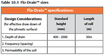
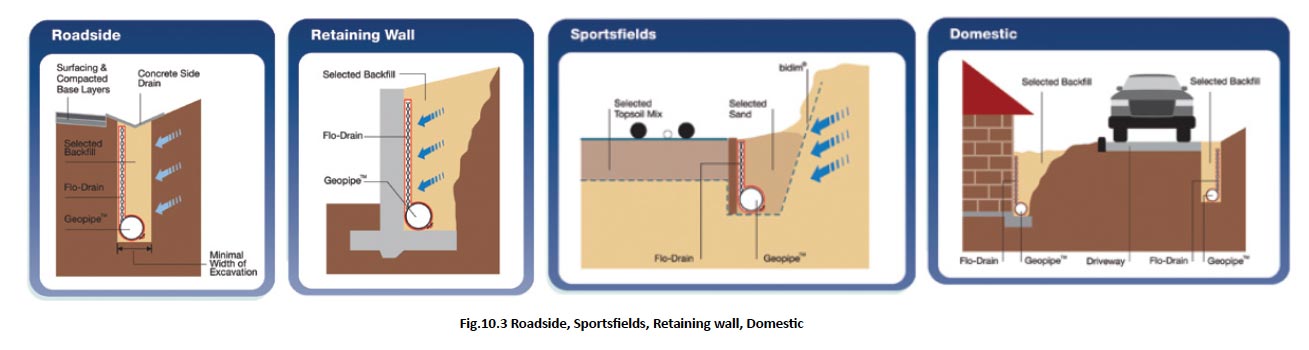
Flo-Drain™ Application
The Flo-Drain™ can be successfully used in the lowering of the water table or intercepting seepage in a wide range of applications:
- Roadside edge drains
- Rail-track formation edge drainage
- Sports fields, golf courses, tennis courts and bowling greens
- Behind retaining walls and bridge abutments
- Behind flexible retaining wall structures
- Around buildings and structures
- Courtyards, embankments and driveways
- Agricultural lands
System consists of bidim® + Flo-Drain™ + Geopipe™. bidim® is a continuous filament needle-punched , non-woven polyester geo-textile. 70% of the Geopipe™ surface area is perforated, giving unmatched infiltration capacity.
On site assembly and installation
- The Flo-Drain™ fin is supplied preassembled (Geopipe™ separately).
- The Geopipe™ is positioned at the base of the fin, solid channel down, and the geotextile flap firmly secured around it, joined by means of a wire, twine or stapling.
- The Flo-Drain™ is placed vertically into the trench and fixed to the side of the excavation or suspended with wire ties from stakes placed across the excavation. By securing the Flo-Drain™, the drain is held in position during backfill placement. The Flo-Drain™ should not be allowed to concertina during backfilling. With selected fill set the Flo- Drain™ against the downstream face of the trench. With unselected fill set the Flo-Drain™ against the upstream face. Backfill must be well compacted in layers. Backfill must be a well-graded, free-draining material.
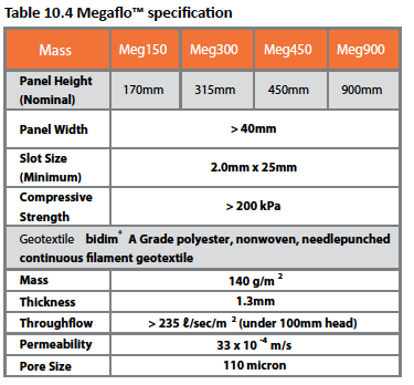
Megaflo™
Megaflo™ is a high strength flow panel drain available in a wide range of sizes each with its own range of fittings.
Megaflo™ installation benefits
- Megaflo™ panel drains are installed in narrow trenches requiring less excavation and reinstatement than conventional drains
- Megaflo™ panel drains are ideal for retrofitting as they cause very little disturbance to the existing roadway
- Megaflo™ panel drains provide rapid response times therefore reducing the time moisture remains in the pavement

Figure 10.4 Megaflo™
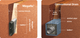
Figure 10.5 Megaflo™ pre-fabricated
Installation
While actual installation procedures are specific to each application, some general guidelines will aid in the successful installation of Megaflo™.
- Excavate trench to the required depth and width enduring that there will be sufficient cover from the surface* to the top of the panel. *Typically, this is between 100mm and 30mm depending on the loading
- Panel location is against the side of the trench from which the infiltrating water is to be drained. Where site conditions result in water infiltration from both sides of the trench, locate the drain in the centre. This will also apply where there is a potential for the side of the trench to be undercut or subside or where there is potential for excessive pumping of subgrade fines
- Backfill around the drain with a free draining compact-able material such as well graded clean washed sand or gravel. Compact to 95% Mod AASHTO in a maximum of 150mm lifts or alternatively wash in sand drainage material then compact. No fines concrete may also be used to backfill the trench
Geotextiles
Design consideration
Geotextile selection is critical when designing with geosynthetics, as the incorrect choice can result in a significant reduction in design life of a project. Having hands-on experience of geosynthetic applications since 1972, Kaytech is able to present the following authoritative tables (based on high elongation geotextiles) giving recommended grades of geotextile that will survive given installation conditions. Engineering judgement must however still be used to assess the severity of the installation.
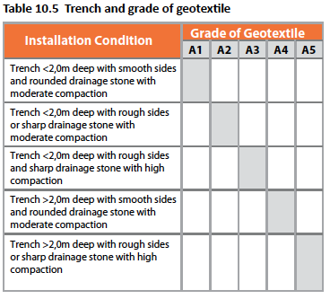
Subsoil Drainage
Hydraulic and Filtration characteristics are the most important factors when using geotextiles in drainage applications. To ensure the properties specified are maintained, the following table can be used to determine survivability requirements.
Hydraulic construction
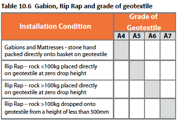
Design consideration
Hydraulic and Filtration characteristics are the most important factors when using geotextiles in hydraulic applications. To ensure the properties specified are maintained, the following table 10.6 can be used to determine survivability requirements.
Subsoil Drainage
Hydraulic and Filtration characteristics are the most important factors when using geotextiles in drainage applications. To ensure the properties specified are maintained, the following table 10.6 can be used to determine survivability requirements.
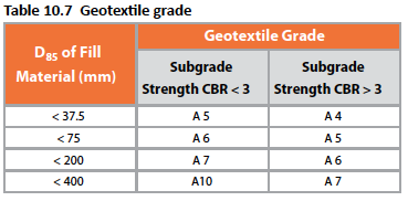
Separation
Strength and Conformability characteristics are the most important factors when using geotextiles in separation applications. To ensure the properties specified are maintained, the following table 10.7 can be used to determine survivability requirements.
Strength and Conformability characteristics are the most important factors when using geotextiles in separation applications. To ensure the properties specified are maintained, the following table 10.7 can be used to determine survivability requirements.
Non-woven Continuous Filament Needle Punched Polyester Geotextile
- Non-woven – High through-flow and excellent filtration
- Continuous Filament – High strength
- Needle Punched – High elongation
- Polyester – Superior chemical resistance
Demolitions
On some building sites, preparing for construction involves the demolition of existing structures, either completely or partly. This may include the removal of buildings, parking areas, swimming pools, driveways, as well as the clearing of trees and bushes where the new structure will be erected. Demolition work is subject to the approval and control by the local authority as described under standards (regulation F9) and proper safety measures must be followed when demolishing structures.
Temporary Site Facilities
As discussed in the section on Safety & General Site Considerations, there are certain temporary site facilities that must be provided, some of which are discussed below and others under standards in terms of the National Building Regulations.
Site huts
Site huts are an absolute necessity if no other water or rainproof, lockable facility is available. They would generally be used for the storage of cement or any other items susceptible to water damage or theft. Depending on the size of the project, site huts are also used for administrative purposes (offices).
It must be noted that regulations are enforced regarding site huts – see regulation (F10) under standards; the onus falls on the building contractor to be aware of these regulations. The regulations would relate mostly to the health and safety of the person occupying the hut, such as security personnel. The type of flooring, adequate ventilation, roofing, etc. would have to comply with the National Building Regulations. Should any accidents occur where the occupant is injured, the building contractor would be held responsible.
Site toilets
Most new building sites do not have toilet facilities; it is regulated that sanitary facilities must be provided for site staff before any work can be undertaken – see regulation (F11) under standards. Sanitary facilities shall be provided at the rate of not less than one sanitary facility for every thirty workers/site personnel concerned.
It is common practice that if the project is of comparatively large scale to construct a temporary facility that is connected to the municipal sewer (conforming to local authority regulations) or to hire portable chemical toilets. Sanitary facilities must be so sited as not to be offensive; they must at all times be maintained in a clean and hygienic condition, and unless they are of a permanent nature, be removed immediately once such building work has been completed.
Temporary roads
In order to gain access around a building site, temporary roads must be considered. In many cases once the building work starts and the structure starts coming out of the ground access becomes more and more difficult, especially for concrete trucks. These roads should not have sharp corners, be level to avoid offloading problems and be kept relatively smooth and well compacted. Where gradients are encountered the gradient shouldn’t be more than 1:9 as anything steeper will make it difficult for fully loaded trucks to pass.
Earthwork
Earthwork usually involves a number of activities, like site clearance and levelling, excavation, backfilling, compacting, stabilizing, creating slopes, and the prevention of excavations from collapsing. These activities are discussed next:
Site Clearance & Levelling
Site clearance is the task of removing any disused structures, bush, trees and other vegetation from the site, while levelling is the activity of levelling the existing ground to provide a level area for the building. The first phase of levelling known as ‘rough levels’ are done to facilitate the excavation and construction of the building, where the topsoil is removed and stockpiled for reuse after the building is complete. The finished levels are done after the building is complete; bringing site elevations up to the levels required on the site plan.
It is important to take cognisance of the fact that removing or importing soil is expensive. Cut-and-fill levelling operations should be carefully balanced to avoid the need of transporting soils. Construction costs can be kept as low as possible by keeping earthwork activities to a minimum by utilising site contours effectively and avoiding large scale excavation and levelling, which also creates dust and the potential for erosion – see figures 8.3 to 8.5 illustrating variations in site levels.
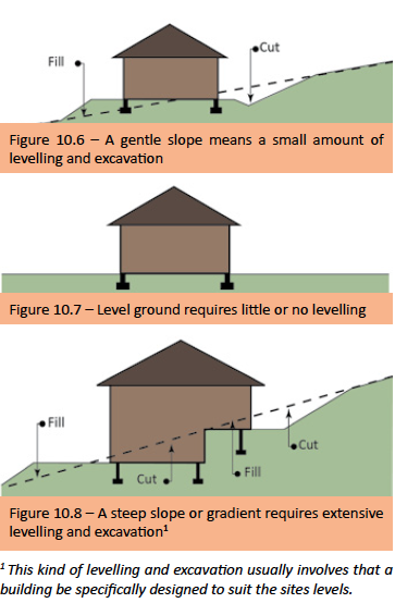
It is also important to remember that site levelling must be larger than the footprint of the building to allow for the construction process to proceed unhindered in terms of access, material delivery and storage, and where required scaffolding bases.
Excavation
Excavations are required for footings, foundations underground services, basements and other aspects of a project. As discussed under plant and equipment a wide variety of plant can be used to perform these different types of excavation. Shallow foundations are usually dug using manpower or in bigger projects using a trencher or backhoe. The depth of the foundation footing is dependent on the soil conditions and the bearing capacity which was discussed earlier in this section. Buildings with basements will involve a large amount of excavation, which includes the removal of the soil excavated.
Multi-story buildings require extensive excavation that can reach a number of stories underground to get to bedrock or other supporting soil with the required bearing capacity. If solid rock needs to be excavated the costs of excavation can become exorbitant where the design of the building might have to be changed to avoid these extra costs. Weak and thinly layered rock can be loosed with backhoes or by using pneumatic jackhammers, which can also be expensive if large amounts of loose rock have to be removed. Deep foundations present the problem of the possibility of collapsing sides. The depth and type of soil and the location of the site influence what strategies one should follow. If the excavation is not too deep and the site is large enough, excavation sides can be sloped. The angel of the sloped surface will vary with the type of soil but should be not greater than 1:2 in accordance with SANS 10400 Part G: Extracts of which are described as follows.
Part G Requirements
The functional regulation G1 (1) contained in part G of the National Building Regulations shall be deemed to be satisfied where the excavation relating to a building a) is less than 3,0 m deep and complies with the requirements of 4.2, or b) is the subject of a rational design or a rational assessment (or both) prepared by a competent person (civil engineering) or competent person (engineering geology).
NOTE 1 – No excavation can be made without causing some movements. Any method of construction that involves vibration, such as blasting, piling or compaction, might cause damage to adjacent buildings either directly from the vibrations themselves or their effect on the underlying soils.
NOTE 2 – In rock excavation, stability is governed more often by the properties of the joints rather than the rock material.
NOTE 3 – The South African Institution of Civil Engineering’s (Geotechnical Division) Code of practice for lateral support in surface excavations provides practical guidance to enable a competent person (civil engineering) or competent person (engineering geology) to comply with the requirements of 4.1(b).
NOTE 4 – Part G of the National Building Regulations is concerned with the safety or stability of any property or service. The Construction Regulations issued in terms of the Occupational Health and Safety Act, 1993 (Act No. 85 of 1993) are concerned with the safety of workers during the construction period. Part G is therefore concerned with the location and geometry of the excavation while the Construction Regulations are concerned with the actual construction of the excavation.
4.2 Excavations
4.2.1 Temporary excavations
Temporary excavations shall not extend below the line shown in (Figure 10.9) drawn from the bottom edge of the foundation of a building.
4.2.1 Temporary excavations
Temporary excavations shall not extend below the line shown in (Figure 10.9) drawn from the bottom edge of the foundation of a building.
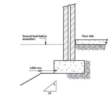
Figure 10.9(a) – Temporary excavations – exposing existing foundations
Note: Surface water shall be diverted away and prevented from running down the cut and causing erosion.

Figure 10.9(b) – Temporary excavations – in close proximity to building
4.2.2 Permanent excavations
4.2.2.1 The slope of cuttings in permanent excavations shall not be steeper than 1:2 (see Figure 10.10), except in the case of sound, intact rock, where the slope of the cutting may be vertical.
4.2.2.2 The excavation shall be sloped so that no water ponds within 3 m of the toe of the cutting.
4.2.2.3 Surface water shall be diverted away and prevented from running down the cut and causing erosion.
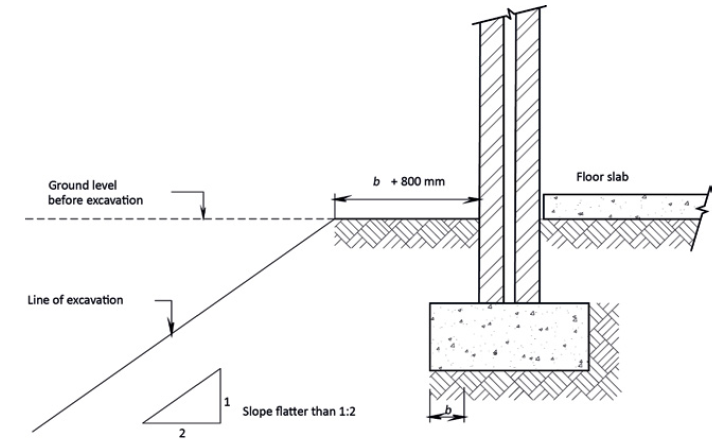
Figure 10.10 – Permanent excavations
Note: The sides of the excavation shall comply with the requirements of the Construction Regulations issued in terms of the Occupational Health and Safety Act, 1993 (Act No. 85 of 1993).
Regulations
G1 General Stability Requirement
G1 General Stability Requirement
- Where any excavation related to a building is carried out or is to be carried out on any site and such excavation may impair the safety or stability of any property or service, the owner of such site shall take adequate precautionary measures to ensure that the safety and stability of such property or service is maintained.
- While any such excavation remains open, and during the placing of any foundation within it, such excavation shall be maintained in a safe condition by the owner or person carrying out such excavation.
- Where the safety or stability of any property or service is likely to be impaired by such excavation, or where the depth, at any point, of such excavation is likely to be more than 3 m, the owner of the site shall :
- (a) obtain the prior written authorization of the local authority for such excavation; and
- (b) take the precautionary measures specified by the local authority or an approved competent person in such authorization.
- The owner of any site shall, at least seven days prior to the commencement of any excavation contemplated in subregulation (1), notify the local authority in writing of his intention to excavate.
- Any owner or person who fails to comply with any requirement of this regulation, shall be guilty of an offence.
G2 Deemed-To-Satisfy Requirements
The requirements of Regulation G1 (1) shall be deemed to be satisfied where the excavation complies with SANS 10400-G.
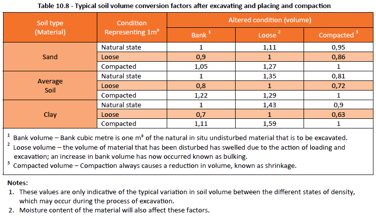
Soil volume
The volume of soil changes as it is excavated, hauled, placed, and compacted. When soil is excavated from its natural state (bank volume) it increases in loose volume known as bulking or swell, and when the same material is brought back for fill, a reduction in the volume of the material takes place, known as shrinkage, mainly due to compaction.
Soil volume also changes due to fluctuations in moisture content. Clays are especially susceptible to changes in moisture – as the moisture content increases, the soil expands and when the moisture decreases the soil will shrink.
The type of soil or material being excavated or placed will influence these bulking or shrinkage factors (as seen in table 8.3 below), but generally for estimating purposes a bulking factor of about 1.2 can be used, and a shrinkage factor of about 0.85 can be used.
Bulking is therefore an increase in the volume of material after excavation and shrinkage is the decrease in volume of material after placing and compaction.
Backfilling
Backfill is required around the foundations after foundation brickwork has been completed and to the underside of the surface bed (before the concrete is placed). Normally the material excavated from the foundation trenches will be used for refilling, but if it is of a type difficult to compact and where potential settlement could occur, it may be necessary to import other fill material; likewise if there is insufficient fill for filling under the surface bed, fill would need to be imported.
This fill is either builders’ rubble (hardcore) or a soil that is suitable and safe to use for a particular application. Your local sand and stone supplier would usually be able to offer guidance in this regard and undertake to transport this filling material to site.
No special consideration is needed where fill has been placed under carefully controlled conditions since the load-bearing characteristics of well compacted fill are likely to be superior to many naturally occurring soils. However, where the fill is poorly compacted, the allowable bearing pressure of the surface soil is likely to be limited by the potential for long term settlement in the fill, especially where there is a flow of water to wash out any granular backfill material.
Remember it is essential that the fill material should be placed and spread in regular layers of not more than about 200 mm in thickness and each layer adequately compacted before placing the next.
It may also occur that fill is needed to either level a site or fill depressions, and where compaction is not necessary.
Compaction
The compaction of soil refers to increasing its density by mechanically forcing the soil particles closer together by forcing out the air and water, using rollers, tampers and vibrators. The amount of compaction that can be gained depends on the physical and chemical properties of the soil as well as its moisture content, the method of compaction, and the thickness of the soil layers being compacted.
As compaction creates a denser soil mass, the effect of compaction can be measured in terms of dry density, i.e. the mass of solid material per unit volume of the soil. Bulk density and the moisture content of the soil are used to calculate dry density.
The level of compaction can be measured both in the field as well as the laboratory. Laboratory tests determine the degree of compaction achievable when using a standard amount of compaction effort, with a view of understanding the probable degree of compaction obtainable in the field.
There are two methods of ensuring compaction to a required specification are achieved:
- The compaction procedure method – specifying the type of compaction plant to be used as well as the number of passes for each layer. This specification is usually provided by the civil or structural engineer when required.
- The end result method – specifying the ‘in-place’ dry density of the compacted soil by using tests like MOD ASSHTO1 or CBR1. How this compaction is achieved is left entirely to the contractor’s discretion, provided the ‘end result’ as specified is achieved. – 1These are the most commonly used tests to determine the strength and density of the soil; the mod AASHTO [] mod=”Modified” ] and CBR (California Bearing ratio) tests. (which are not discussed here)
Soil Stabilisation
Soil stabilisation can be considered to be any process that may improve the condition of a soil and make it more stable. Some of the important advantages of stabilisation are:
Soil stabilisation can be considered to be any process that may improve the condition of a soil and make it more stable. Some of the important advantages of stabilisation are:
- The strength of the material is increased
- The durability and resistance to the effects of water are improved
- Wet soils can be dried out
- The workability of clayey materials can be improved
Often the construction of road bases and surface courses which are not suitable have to be stabilized to improve the strength, durability and loading capabilities of the soil.
Soil stabilisation can be achieved by using one or more of the following methods:
- Blending soils
- Mechanical stabilisation
- Cement stabilisation
- Lime stabilisation
- Bituminous stabilisation
It is not the aim of this subsection to provide an in-depth discussion on stabilisation. The process of soil stabilisation is dependent on a number of variables outside the scope of this book and requires the professional assistance of a suitably qualified person to specify the actual process required for a particular application; the reader is therefore advised when required to seek proper guidance in this regard.
Slopes
A slope in engineering terms is any inclined surface to the horizontal. Slopes may seem insignificant when considering the excavation of platforms and different levels for a site; however it is important that slopes be given careful consideration in regard to moisture content and erosion. A fairly common failure is slipping of an embankment or cutting, because of the presence of water, either by erosion or by increasing the moisture content of the soil reducing the shear strength. Therefore the protection of newly created or cut slopes from conditions such as wind and rain is important.
Slope protection
There are various ways to protect slopes from collapse the most important being controlling the moisture in the soil. Suitably designed drainage must therefore be implemented where slopes have been created to minimise any seepage pressure. Slopes can be protected by using one or more of the following methods:
- Gabions – Large aggregates placed in a wire cage, packed on the slope, with soil used to fill behind the cages.
- Hydro-seeding – Plant seeds are mixed with nutrients and fertilizer and using a specially adapted machine, sprayed at a fairly high pressure into the soil, ensuring germination.
- Rip-rap – Like gabions, it also uses very large aggregates but the difference lies in that the aggregates are placed loosely by hand.
- Planting – Planting of quick growing shrubs, grasses and ground-covers along the slope in order to stabilise the soil and protect it.
- Straw covering – A temporary means of protecting the slope until a more permanent method of stabilisation is used or until the soil stabilises itself naturally through the growing of grass and other plants.
- Polyjute (soilsaver) – The installation of a non-woven polypropylene textile placed directly on the slope providing immediate protection from wind and/or rain and runoff erosion problems, while forming a biodegradable, protective host for vegetation establishment and future growth.
Prevention of Excavations from Collapsing
Care must be taken when excavating trenches and the like for a building. The soil may be of a loose nature and become easily saturated and susceptible to collapsing. To prevent unnecessary collapsing of trench sides and concrete over-break, it would be recommended to support the sides before pouring the concrete to eliminate this problem.
Blasting
Many parts of South Africa have considerable rock formations extending below the surface of the ground. Before a foundation or services like sewerage pipes or other subsurface work can begin, it is sometimes necessary to blast out rock located in an excavations path. Drilling and blasting is expensive and a careful analysis of the site must be made during the tender phase of the project. When an area known to contain rock, soil testing must be done to determine whether blasting would be required before construction work commences.
Blasting requires the services of a suitably qualified person(s) to carry out such work and is regulated in terms of the National Building Regulations, SANS 10400 Part G, described as follows:
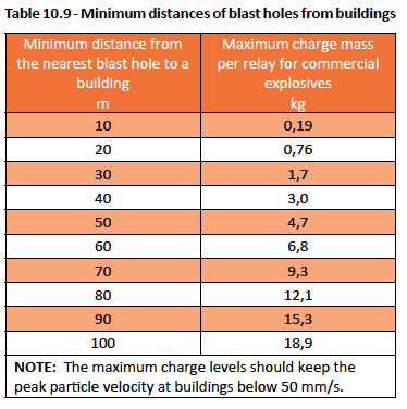
- The distance from a blast hole to the closest point of a building, other than a historical monument or buildings with a foundation system that does not comply with the requirements of SANS 10400 – H, shall be not less than that given in table 10.9 below.
- Detonating relays shall have at least a 20 millisecond delay interval.
Dewatering Techniques
Dewatering is the process of lowering the level of subsurface water on a site to allow excavation work to occur in a dry and stable environment. Sub-soil water can be detrimental to the foundations of a building and for this reason it must be addressed before any building operations start on the site. Dewatering usually begins before excavation and continues as the excavation proceeds. Subsurface water is removed by using one of the following techniques:
Sub soil drainage
In order to keep the ground floor under a building dry in waterlogged areas, a sub soil drainage system should be installed to drain the surplus water to a drainage sump. A network of pipes is laid under or adjacent to the building in a herringbone pattern to collect and drain the seepage water away from the footprint of the building. These pipes are usually manufactured from uPVC or pitch fibre with small holes drilled at approximately two thirds up on the outer circumference of the pipe (known as perforated pipes) to allow the water to filter into the pipe.
These pipes are then laid in a narrow trench to a reasonable gradient and at least 100mmm below the bottom of the foundation bed to ensure a proper drainage of the sub-soil. The pipe is then covered with a filter (geo textile) fabric and filled with small stones for approximately 300mm in height (an agricultural drain) with the upper layer filled with a finer type soil and when outside the footprint of the building grass would then be planted on top.
The pipe network flow is taken to a sump where surplus water can be collected and pumped to either the street level or even used for irrigation purposes. These sumps are fitted with a centrifugal pump where the drainage of water is of constant flow; or if not of constant flow a suitable soak-away can be used effectively.
Well points
A well point is a perforated unit placed at the bottom of a pipe that is driven into the soil around the perimeter of the proposed excavations. A series of well points are then driven into the soil connected to horizontal pipes above the ground, called headers, which are connected to centrifugal pumps that draw water up into the header pipes and eject it for drainage away from the excavation.
Retaining walls
Retaining walls are required in a number of civil work applications including smaller site works and excavations. These walls are specialised forms of construction with specific performance requirements and there is a large amount of technical literature dealing with retaining walls, and more specifically concrete retaining walls available from the likes of the CMA (Concrete Manufacturers Association). These applications are outside the scope of this publication. In this section a brief description is given of some relevant matters concerning the use and types of retaining walls.
The basic function of a retaining wall is to retain or support soil at an angle greater than it would naturally assume, usually at a vertical or near vertical position. The design of any retaining wall is basically concerned with the pressures of the retained soil and any subsoil water. Retaining walls must be designed to ensure that:
- Overturning does not occur
- Sliding does not occur
- The soil on which the wall rests in not overloaded
- The potential for the build-up of subsoil water behind the retaining wall is avoided by installing a natural drainage system behind the wall
Typical uses for small retaining walls are to provide near flat ‘terraces’ in a sloping site for platforms or gardens or access paths. Small is defined here as up to 2.00m. Retaining walls are generally constructed from masonry or concrete and may be reinforced or unreinforced. For small walls, calculations are not normally necessary and typical sections of masonry wall are accepted as suitable for the relatively small disturbing forces that will act on them in accordance with the National Building Regulations SANS 10400 Part K.
If any one or more of the seven factors described below apply to a retaining wall, the advice of a civil or structural engineer, or a similarly qualified person should be obtained.
- The wall is higher than about 2.00 m above the top of the foundations
- There is supporting backfill on which banked up soil, stored materials or buildings are to be placed close to the wall
- The wall is higher than about 2.00 m above the top of the foundations supporting backfill on which vehicles or other heavy items will stand or pass close by
- Retaining soil with a slope adjacent to the wall is steeper than 1 in 10
- The wall is supporting a fence of any type other than a simple guard rail
- The wall retains very wet earth, peat or water; for example a garden pond
- The wall forms part of or adjoins a building
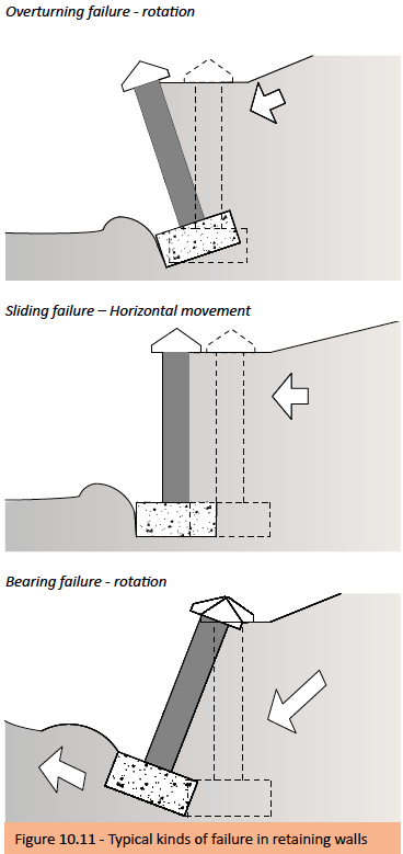
For large retaining walls, methods of calculation need to be established by a suitably qualified person to ensure adequate factors of safety against the common kinds of failure as illustrated in Figure 10.11 are avoided; which are outside the scope of this publication.
Types of retaining walls
There are various types of retaining walls – the more common being:
- Gravity retaining walls
- Cantilever walls
- Precast concrete retaining walls (CRB)
Gravity retaining walls – These walls are also often referred to as mass retaining walls as they rely on their own mass and friction (dead weight) on the underside of the wall to overcome the tendency to slide or overturn/rotate. These walls when small can be constructed from bricks, stone or reinforced concrete. Higher walls, especially those constructed using brickwork or stone must be reinforced with a reinforced concrete core.
Cantilever walls – These walls are normally constructed of reinforced concrete so that the vertical stem can be relatively thin. In a cantilevered wall the stem is supported solely by its connection to the base by using spread foundations, where the weight of some of the retained soil contributes to the overall stability of the wall. Two basic forms can be considered – base with a large heel or, if this is not practical, a cantilever wall with a large toe, or even both. Buttressing may also be added to either the inside, or sometimes the outside, face.
Precast concrete retaining walls – In recent year’s dry stack concrete block retaining systems have come into common usage and are commonly known as CRB (Concrete Retaining Block) walls. In many instances CRB walls are being used in preference to conventional reinforced concrete walls. The CRB walls can be divided into three groups of retaining walls.
- Conventional gravity CRB walls resist destabilising forces due to retained soils, solely through the self-weight of the CRB units combined with the weight of any soil within the units and the batter of the CRB units.
- Soilcrete enhanced gravity CRB walls are walls in which the effective depth and self-weight of the CRB wall is increased by cement/lime stabilising of a prescribed depth of soil behind the CRB units to form soilcrete.
- Soil-Reinforced CRB walls are composite retaining systems consisting of CRB units in combination with a mass of soil stabilised by horizontal layers of geosynthetic reinforcement materials.
Essentially CRB walls comprise precast concrete blocks, which are stacked row upon row with a prescribed backward offset to form a retaining wall with a specified backward slope. Typically the slopes of the conventional CRB walls range between 55° and 70° (degrees) to the horizontal. During construction, each row of blocks is then filled with soil in conjunction with the placement and compaction of backfill behind the wall.
Building on a site
Building on a site is not simply a matter of finding a design and a site to suit ones needs. There are many aspects to consider and look out for; such as the gradient or slope; north orientation (the general direction that a building faces) – avoidance of western sunlight and where local climatic conditions determine the importance of orientation; entry; building lines and servitudes; view and shape. The combination of all these aspects on a site is more complex than one would imagine and are discussed below.
Gradient or slope
Most sites have a gradient or slope which can be very deceptive. A site that looks level could have a gradient of two meters. Sites with steep gradients are more difficult and therefore more costly to build on, but if designed correctly, a house can be very attractive when incorporating a gradient. A house on a gradient will obviously have stairs. Entry on a steep gradient is important when considering easy access to the parking area.
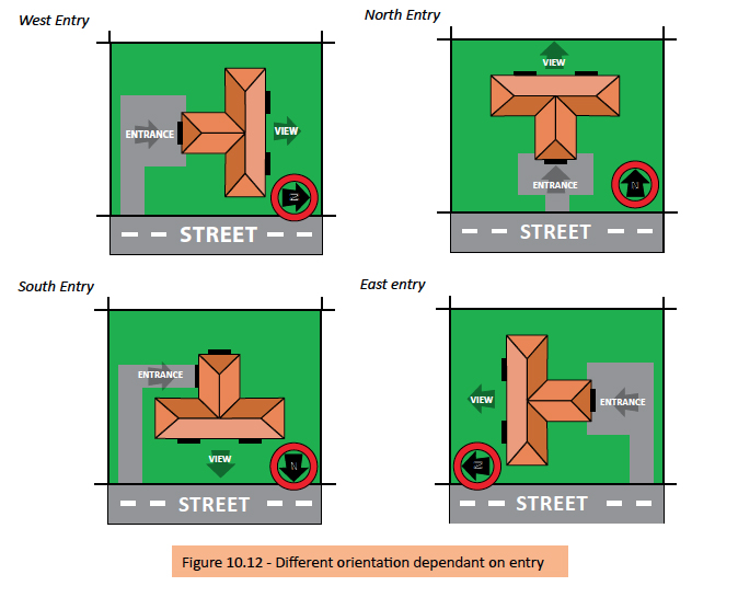
Entry
Entry is a very important factor and in the southern hemisphere it is preferable to have the entry on the southern, eastern or western boundaries, allowing one to take full advantage of the northern portion of the site for living and entertainment areas. In some developments, sites are restrictive in terms of entry, which can affect the layout and orientation of the building.
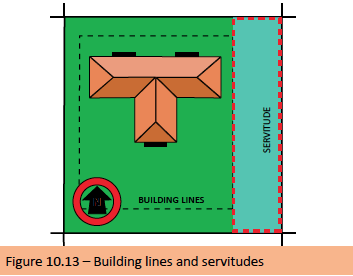
Building lines and Servitudes
One needs to be aware of the building lines and servitudes when viewing a site. A site could have a six meter building line, leaving very little space for building. While a servitude is the part of a property that can’t be built on, usually because of stormwater, electrical or sewerage services and can impact on the overall design of a building and that of external works like swimming pools. It is however, very uncommon for a servitude to run right across the middle of a site, and will usually run along a boundary.
Note: Information on building lines and servitudes can be sourced from your local authority – also see Building lines and Boundary pegs later in this section.
View
Not all sites have a view, but if one is fortunate enough to have a view, one should take full advantage of it. A southern view does tempt a designer to place the living and entertainment areas on the southern side of the house, leaving them in permanent shadow and making the house cold. A site with a western view can cause complications because of the harsh afternoon sun penetrating the rooms on the western side. A site with an eastern view will get the morning sun, which is not as harsh as the afternoon sun, but will leave the rooms in shadow in the afternoon. The ideal view is north – see orientation.
Orientation
The building owner needs to consider the local site environment and the orientation of the building from the outset of the design to optimize energy efficiency. Orientation and climatic conditions have an important role to play when determining where a building should face. For example, a building in the southern hemisphere facing north will be warmer in winter, but in a hot climatic region, one may want to avoid the building facing north and rather face it south. Where ideal orientation is not possible, as is often the case, especially with higher density urban developments, or sites with views, energy efficient buildings can still be achieved with careful attention to design.
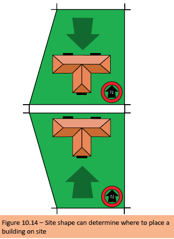
Shape
The shape of a site can also be restrictive, particularly when the northern boundary is the shortest, or the view is on the shortest boundary. Most sites are rectangular, but it is possible for a site to be triangular or to have up to six straight boundaries.
Setting out procedure
Datum Peg and Site Levels
Before starting any building work it is essential to relay site levels from a benchmark or to establish a datum peg from where all site levels will be taken. Typically a municipal manhole in the street closest to the site can be used as a datum. Alternatively a datum peg can be established on the site where a mild steel peg is cast in concrete and marked; however proper care must be exercised so that the peg is not disturbed during the construction process which could lead to a myriad of problems in regard to levels to floors, drainage etc.
The following extract from the National Building Regulations SANS 10400 Part A is offered as further guidance on site levels. A12 Street Levels
- Where any building is to be erected on a site abutting a constructed street the owner of such building shall, subject to the requirements of subregulation (3), erect such building in accordance with the levels of such street
-
- (a), Where any portion of any street abutting the site on which any building is to be erected has not been constructed the owner of such building shall request, in writing, from the local authority the levels at which such portion of the street is intended to be constructed.
- (b), The local authority shall, where in its opinion it is practicable for it so to do and within 21 days after receipt of a request contemplated in paragraph (a), supply the required levels.
- (c), If the local authority is unable to comply with the provisions of paragraph (b) it shall notify such owner, in writing, to that effect.
- Where any street has been constructed, but in the opinion of the local authority is likely to be reconstructed at levels different from its existing levels, the local authority shall give notice of such fact to such owner, and in such notice it shall, if possible, supply the levels at which such portion of such street will be reconstructed.
The dumpy level
A dumpy level is commonly used to establish accurate site levels, excavations, drainage levels and many other related levels of a structure from foundations to windows to wall plate. A Dumpy level comprises the telescope, tripod and staff.
The telescope is mounted on an adjustable tripod, which can stand on any rough terrain by means of adjustable legs and is adjusted so that the telescope is more or less level. Once this is achieved, at the top of or on the side of the telescope barrel is a small spirit level which needs to be made level by adjusting the foot screws of the dumpy level until the air bubble is exactly in the centre of the calibration marks. After this adjustment, the telescope is swung through 90° (degrees), facing the other foot screws. The adjustment procedure is then repeated until the air bubble is dead centre in the circular bubble.
In the eye piece of the telescope there are four cross hairs which are adjustable by rotating the eyepiece itself in order to obtain a better image of the cross hairs; just like any other telescope the focus can be adjusted by using the focusing knob in order to obtain a clearer image of the reading on the staff. The reading that should be taken on the staff is in line with the middle horizontal hair in the eyepiece. To check that the reading taken is correct, a spot check can be made by reading the upper and lower hair readings; the total of the top and bottom hair readings, divided by two, should equal the middle reading on the staff.
The staff is approximately 1.80m long when not extended; it can be extended to almost three times this length when the three sections are fully extended.
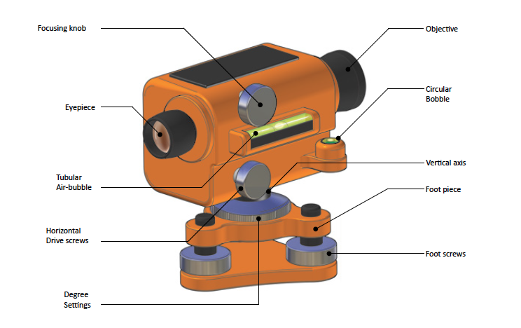
Figure 10.15 – Diagram of a typical dumpy level
Building Lines and Boundary Pegs
Building lines can be defined as a line prescribed in any town planning scheme or any other by-law designating the boundaries of the area of the site outside of which the erection above ground of any building is prohibited. In cities building lines vary depending on local council town planning schemes like zoning, street widths or any other local authority by-law. In rural areas this is seldom an issue as measurements can exceed hundreds of meters from the road or site boundary.
Building lines can only be established if boundary pegs are visible and have been accurately identified. The SG diagram and site plan will usually assist in this process; however it can happen that boundary pegs cannot be found, and the owner would then need to engage the services of a land surveyor to establish these beacons as highlighted below in an extract from the National Building Regulations SANS 10400 Part A.
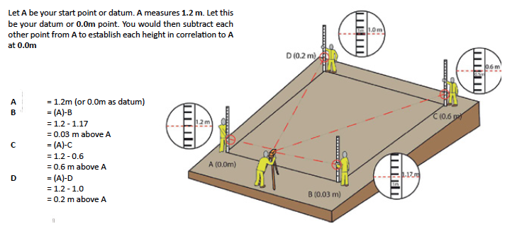
Figure 10.16 – Typical method of establishing levels on a site
A11 Pointing out of Boundary Beacons
- Where, in the opinion of the local authority, the location of any boundary of a site has not been accurately determined such local authority may require the owner, at his own cost, to engage a professional land surveyor and to submit to the local authority a certificate, in an approved form and signed by such professional land surveyor –
- (a) identifying the boundary pegs or beacons of such site;
and - (b) stating the name of the nearest cross street and the approximate distance of the nearest boundary of the site from such street.
- (a) identifying the boundary pegs or beacons of such site;
- Where such owner fails to engage a professional land surveyor as contemplated in subregulation (1) the local authority may engage a professional land surveyor to establish and point out the location of such pegs or beacons, and the local authority may recover such costs of such establishing and pointing out from such owner.
Setting Out and Building Orientation
It is usually the task of the building contractor to interpret the building layout on site using the site plan and working drawings. The building is orientated in accordance with what has been shown on the site plan which will show the North Pole and the street. The following points should then be followed:
- The building faces as orientated on the approved site plan.
- The building is set out on the correct stand
- The overall dimensions correspond with the plan dimensions
- The building is set out within the required building lines.
Setting out by means of the 3-4-5 method
The first step is to mark out the building lines (a ranging line depending on the site and structure) from the boundary line of the stand, by taking measurements from the boundary line using a tape measure (these measurements must be accurate and taken from known boundary pegs) to the building line as shown on the site plan.
Then mark out the overall length of the structure by driving in pegs at points A and B as indicated in the example below.
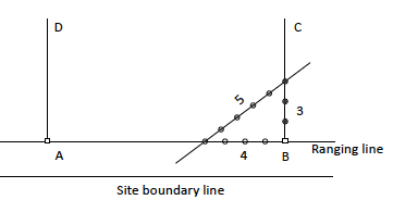
As soon as the total width of the structure is determined run a string from peg A to peg B. Mark off on this line from point B to A a 4 metre length using a tape measure and drive in peg C. Mark off from peg B to C a length of 3 metres in the direction of peg C, which is still unknown. Then shift peg C until the measurement of the diagonal line as shown above measures a length of 5 meters then only drive in Peg C. You should then have an accurate square (90 degree angle) where other measurements can be taken from to set out the proposed building.
Setting out using a theodolite
A structure can also be set out using a theodolite, which is more accurate because all relevant angles and dimensions are established using this machine. However they are seldom used on smaller projects as they must be operated by a suitably qualified person and are usually only used on bigger projects.
Note: For more information on Setting out and Building orientation see the Foundation Section
References
Alexander G C. 2010. Energy Saving Building Solutions. Johannesburg: Buildaid Publishing.
Alexander G D & Van As F. 2008: Civil Technology. Johannesburg: EWA Publishing.
Concrete Manufacturers Association – www.cma.org.za
Harrison H W & Trotman P M. 2002. BRE Building Elements – Foundations, Basements & External Works. London: Construction
Research Communications Ltd.
Julyan E L. 1998. Building & Civil Technology. 2nd Edition. Johannesburg.
South African Bureau of Standards. 2011/12 – SANS 10400 Part’s A; F; G; K and R. Pretoria. SABS Standards Division.
Spence, W & Kultermann, E. 2011. Construction Materials, Methods & Techniques (International edition). Third edition. USA.
Cengage learning.
Van Amsterdam E. 2009. Construction Methods for Civil engineering. Cape Town: Juta & Co.
Van Amsterdam E. 2010. Construction Materials for Civil engineering. Cape Town: Juta & Co.