Chapter 12
FOUNDATIONS
Soil Conditions
Ground Improvement
Foundation Types
Lateral Support
Concrete
Cement
Aggregates
Manufacturing Concrete
Concrete Tests
Reinforced Concrete
The Foundation Process
Installing Thermal Installation
Introduction
As the name implies, it is the foundation which supports the part of the building which sits on the ground, to carry the substructure and superstructure. Foundations are typically built below ground and form the base for any structure. Their function is to distribute the load of the structure into the soil. Foundations can also be referred to as bases or footings.
Terminology
Setting Out
This is the term used for interpreting the floor plan drawing onto the site – placing marks to show where the work is to be located.
Foundations
The term foundation is sometimes incorrectly used to refer to certain elements within a structure. The term is a general reference to all the elements that make up the foundations, i.e.: including the ground that supports the structure and all elements between the ground and the superstructure (See – substructure). As an example in a residential project, the trench and soil/gravel/rock beneath the trench, concrete strip footing and foundation brickwork will be referred to as the foundation.
Substructure
The part of the building structure (elements) below ground level, the foundations and basements. Substructure work is a critical activity; once it is completed the building is out of then ground and the superstructure can commence.
Settlement
Refers to ground movement and can be caused by deformation of soil due to loads imposed on it.
Mortar (dagga)
A specific mix of sand, cement and water, used for bricklaying and plaster.
Aggregate
Aggregates is the term used for the sand or stone pieces that can be mixed with cement and water to make concrete or mortar
Trench
Once setting out is complete, trenches are dug (approximately 600mm in width), and at least 550mm deep. This allows for a footing of approximately 250mm deep and 300mm from ground level. Depending on how much load a foundation will have to bear, and the strength and bearing quality of the underlying soil/gravel/rock, trenches differ in size.
Footing
A footing refers to the concrete inside the trench – this forms a base for the rest of the brickwork or other materials in the foundations and for the entire superstructure. The footing is also referred to as a strip footing.
Backfill
The material from the site that if suitable, will be used to fill in around the substructure.
Dumpy Level
A dumpy level is an instrument used in surveying and building to set horizontal heights/levels. The instrument requires to be set level (using a spirit level) in each quadrant, to ensure it is accurate through a full 360° traverse. As an alternative, laser levels have been developed to provide the same height transfer purpose.
Reinforce
Strengthen or support an object or substance, specifically with additional material, usually steel.
Reinforced Concrete
Concrete which has steel bars or wire embedded to increase its tensile strength.
Reinforcing
Reinforcing is used throughout the building process to support and or strengthen the structure. There are various types of reinforcing and each has a specific use – whether in brickwork or for a concrete slab. It is vital that reinforcing is kept clean of all organic material (such as mud and grass) and not rusted, because this material could cause damage to the mortar. All reinforcing in a building is designed by an engineer.
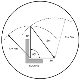
3-4-5 Method [for setting out position of foundations]
This is a method used to ensure that a right angle is achieved. It is based on the fact that if one has a 3m length of string and a 4m length of string, that the two will form a right angle when joined by a 5m length of string to form a triangle.
Tensile strength
The resistance of a material to breaking under tension

Compressive strength
The resistance of a material to breaking under compression

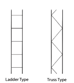
Brickforce
Light welded material made up of two hard drawn wires (not less than 2.8mm in diameter, not bigger than 3.55mm in diameter), joined at regular intervals either at right angles (ladder) or diagonally (truss type) cross wires. The most commonly used type is the ladder type.
Expanded Polystyrene (EPS)
EPS is used for thermal insulation in foundation walls and floor slabs (SOG [Slab on ground]) as sheets or boards. Loose beads of EPS can also be used as an aggregate for lightweight concrete, plaster or renderings. EPS can also be used for permanent formwork, prefabricated and foundation walls, under floor heating and drainage boards
Foundation formwork
As the name suggests, this formwork is used in foundations where subsoil conditions are unstable. Formwork is strutted against the excavation faces to provide a consistent (form) preventing irregular shapes or even collapse when the wet concrete is poured.
Tools
Tape Measure
Steel tapes (either roll up or spring loaded wind-up). A tape measure is made from a strong, thin ribbon of steel, wound up into a metal or plastic casing. Longer tape measures are usually made of vinyl. Tape measures are made in lengths ranging from 2 metres to 100 metres. They are marked in millimetres, centimetres and metres.
Steel Square
Used to assist in squaring corners, specifically for setting out and setting corners of brickwork. Also used for plastering (reveals, cornices, etc.)
Building Line/Fishing Line
Building line is nylon, the same as used for fishing. Used to assist in setting out a building, to mark the extent and interior of a buildings walls and foundations. Building line is also used between profiles or corner brickwork to ensure that bricks are laid straight.
Straight Edge
A straight hardwood plank (also available in aluminium), planed all round, usually about 100mm wide and between 1 – 3 metres long. Used to level off concrete, plaster and floor screeds or to check surface area for consistency.
Steel pegs
For setting out, pegs are required for corners as well as marking the depth of concrete footings. The best size to use is 8mm diameter mild steel reinforcing rods, cut into 500mm lengths.
Spirit Level
Made of either steel, aluminium or wood a spirit level contains openings which are closed with glass and hold vials filled with alcohol. When the level is on a completely level surface, the bubble formed by air in the vial will move to the middle.
Gauge Rod
This is made up of a straight piece of timber, steel or aluminium, which has markings that equal the height of a brick course (a brick course is the height of a brick plus the mortar on top). A Gauge rod assists in ensuring that brick courses are all the same as they are built up from the foundation. The most commonly accepted measurement for a brick course (gauge) including mortar is 85mm.
Plumb Bob
Made from heavy metal, the plumb bob is hung from a piece of line and when suspended from a level horizontal place, is able to determine if a surface is vertical.
Pick
Used for loosening soil when digging a foundation trench.
Spade
A spade is mainly used for shoring the edges or walls of a foundation trench.
Square nose shovel & Round nose Shovel
For picking up discarded soil, and for loading.
Builders Wheelbarrow
For transporting soil, cement, sand to and from area of building.
Hose Pipe
To transport water from tap to mixing site.
Gloves
Protection for hands when handling cement and bricks.
Concrete Mixer
For mixing concrete on site (mechanically).
Dumper
This is like a mechanised wheelbarrow and able to carry larger quantities of concrete.
Compaction plant
Compaction plant is designed to compact filling material and surface finishes and is influenced by a number of factors. The type of compaction required depends on the situation and local soil conditions. Civil contactors use large compaction equipment specifically for this type of work e.g. vibratory rollers or pneumatic rollers. Whereas building contactors us smaller equipment e.g. plate compactors or mini vibrating rollers (commonly referred to as bomags).
Vibrator
A device called a poker vibrator is used to facilitate the compaction of fresh concrete. They come in various sizes ranging from 25 to 150mm (60 or 75mm are more popular). Poker vibrators are powered by petrol/diesel motors, electricity or compressed air.
Standards
Any building should be designed to provide strength, stability, energy efficiency, serviceability and durability in accordance with accepted standards. The design of the structural system of any building should be carried out in accordance with SABS 0160 (for loads) and SABS 0164 (for structural masonry).
However, “deemed-to-satisfy rules” for single and doublestorey buildings (with certain limitations) are covered in: SANS 10400: The Application of the National Building Regulations, and; National Home Builders Registration Council’s Home Building Manual.
Extract from SANS 10400 (Part H)
Empirical rules apply to buildings not exceeding two storeys in height and with loadings not exceeding those detailed in building limitations for empirical design, except in cases where the founding material is heavy soil, or shrinkable clay or a soil with collapsible fabric. These rules include that:
- Walls are to be placed centrally on foundations.
- Concrete should have a compressive strength of at least 10 MPa or be mixed in proportions (by volume) not weaker than 1 part of cement to 4 parts of sand to 5 parts of coarse aggregate.
- Any continuous strip foundation shall have a thickness of not less than 200mm.
- The minimum width of any continuous strip foundation shall not be less than 600mm for a wall supporting a roof covered with concrete tiles, clay tiles or thatch; 400mm for a wall supporting a roof covered with metal or fibrecement sheets or metal roof tiles.
SABS 10161: The design of foundations for buildings contains recommendations with regard to site investigations and inspections, materials, design considerations, earthworks and excavations, and foundation types.
Extract from SANS 204
This specifies the design requirements for energy efficiency in buildings.
4.4.2 Floors
4.4.2.1 With the exception of climatic zone 5, buildings with a floor area of less than 500 m² with, a concrete slab on-ground shall have insulation installed around the vertical edge of its perimeter which shall:
- a) have an R – value of not less than 1,0
- b) resist water absorption in order to retain its thermal insulation properties, and
- c) be continuous from the adjacent finished ground level
1. To a depth of not less than 300 mm, or
2. For the full depth of the vertical edge of the concrete slab-on-ground.4.4.2.2 Where an in-slab or in-screed heating system is installed it shall be insulated underneath the slab with insulation having a minimum R – value of not less than 1,0.
Note: These standards make reference to a number of other standards which are indispensable for the application of these standards.
Soil Conditions
Outline
Soil conditions play a very important part when excavating foundations for a building. The nature and bearing capacity of the soil influences the structural requirements of a building and any settlement of the soil needs to be taken into consideration. For these reasons it is of great importance that we understand that not only climatic conditions play a part, but that the soil conditions regarding the soil structure is subjected to the required bearing load. Specific soil types are not discussed in this book and it is always recommended that the services of a geotechnical or structural engineer be used in assessing the soil conditions before any building work commences.
Vegetable Soil (Top Soil)
The (top) surface layer of most of our soil is a layer of decomposed matter (vegetation, plant life etc.). This thickness of ground is usually very soft and easily compressible. Any (top) surface soil should be removed before any excavations commence or any foundations are poured.
Sub-Soils
A variety of sub-soils are present in South African conditions, and they need to be assessed before any sort of foundation can just be placed in position to carry a specific bearing load. The hardness of these soils vary considerably from clay, sand gravel and many types of rock strata and may range in particle size from large stones to colloidal clay. The type of soil is therefore a significant factor to deal with when designing the structure. Some of the above mentioned soil types could be easily compressed, whereas others may be very hard.
Sandy Soil
Buildings can be built on sand, but the design should spread the bearing load evenly; in which case a reinforced raft foundation would suit these conditions better than a wide strip footing. Sand is unstable and needs to be mixed with other suitable materials before compaction, to provide better strength.
Clay soil
Clay soil remains wet underneath the foundations and SOG (slab on ground) which is very unstable to the structure. Furthermore clay soils expand (heave) when wet and contract when dry. Foundations for these soil conditions would usually necessitate deep or raft or piled foundations, increasing the costs of the building.
Filled ground
Filled ground does not always provide the strength required to carry heavy loads. The filled ground depends on the type of ground used for the filling and the quality thereof. The material used when filling must be suitably compacted in layers to avoid settlement of the ground.
Filled ground like refuse dumps or landfill sites, are not recommended for any types of buildings due to settlement of the organic matter and the possibility of high instances of methane gas coming from the ground. Geotechnical testing of the soil in these conditions must be obtained before any proposed buildings will be approved by the local authority.
Swampy soil
Swampy or waterlogged ground is not suitable for any type of foundations. And should it occur in certain circumstances that no alternative site is available, Sub-soil drainage needs to be put in place before any excavation can start and test holes would need to be excavated to determine if the ground is stable enough to carry the proposed loads.
Rocky ground
Rocky ground is hard and durable, and performs well as a base to carry considerable loads. However, boulders and rock outcrops can present a problem and may need to be excavated, which will increase the costs of the foundation and building. It is recommended that the services of a structural engineer be used in conditions like this.
Ground Improvement
Many sites, while potentially suitable for development, are underlain by soils, the properties of which would make the development uneconomical using conventional construction methods. Examples of these sites include rock dumps, uncontrolled fills, waste disposal sites, deeply leached residual soils and aeolean sands. These materials are unstable in their natural state due to their compressibility and settlement that could occur with change in moisture content. With correct treatment, these materials can be over-consolidated to provide bearing capacities which allow conventional construction techniques to be employed.
Dynamic Compaction
Dynamic Compaction is an in-situ compaction technique that has been successfully used by FRANKI in projects throughout Southern Africa. The technique involves the in-situ compaction of soils to depths of up to 12m using pounders to impart high energy compaction. The choice of pounder and drop height depends on site conditions, compaction depths and materials to be compacted. Available pounders vary in mass from 7 to 15 tonnes. Using high capacity crawler mounted cranes, the pounders are dropped from heights of up to 22m to achieve the desired compaction depth.
Dynamic Compaction is normally used under the following circumstances:
- To increase in-situ density and in this way improve the bearing capacity and consolidation characteristics of soils (or waste materials) to allow conventional foundation and surface bed construction to be carried out.
- To increase in-situ density and in this way improve in-situ permeability and / or reduce liquefaction potential.
Not all material types are suitable for Dynamic Compaction. Under these circumstances Dynamic Replacement can often be utilised. In this technique a selected material is driven to partially or completely displace the unsuitable in-situ material to form columns of compacted material which transfer the load onto underlying more competent horizons. Generally a blanket or raft of selected material is compacted at surface to effectively transfer the loads onto the compacted columns.
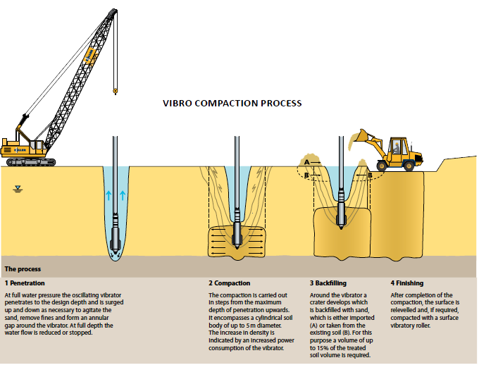
Vibro Compaction
Vibro Compaction is a technique that compacts granular soils and rearranges the soil particulars into a denser state. The compaction is attained using depth vibrators, typically suspended from a crane or mounted on piling equipment.
Vibro Compaction increases bearing capacity for shallowfooting construction, reduces settlements and also mitigates liquefaction potential in seismic areas. Natural or manmade deposits of sand and gravel are frequently not dense enough or are too inhomogeneous to allow a proposed structure to be safely and reliably founded. Using depth vibrators the soil density can be increased and homogenized independently from the groundwater table.
Applications of Vibro Compaction
- Suitable for granular soils with a fines content of less than 15%
- Foundation pressure up to 1Mpa can be safely carried
- Off-shore compaction of sea bed
- Liquefaction mitigation
- Sinkhole remediation
- Deification of embankment zones and excavation bases to reduce permeability
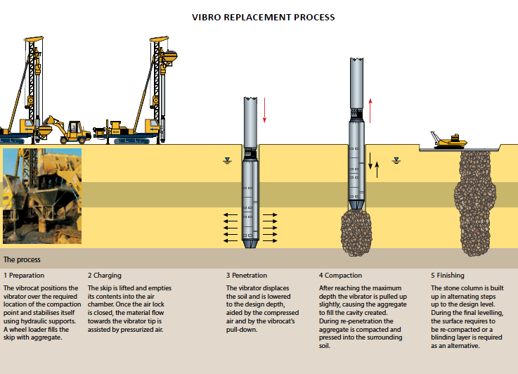
Vibro Replacement
Vibro Replacement is a method of constructing densely compacted stone columns using a depth vibrator to densify the aggregate backfill and surrounding granular soil. The technology is used to treat clays, silts and mixed stratified soils and improve their load bearing and settlement characteristics. Stone is introduced either down the side or from the tip of the vibrator and is compacted bottom-up in controlled stages. The stone columns reinforce soft soil, accelerate drainage and mitigates liquefaction due to a seismic event.
Typical applications for stone columns include settlement and stability improvement below embankments and stockpiles; foundations for all type of building especially warehousing and industrial buildings; wind turbines and liquid storage tanks.
Applications of Vibro Replacement
- Suitable for very weak, cohesive and organic soils.
- The allowable bearing pressure after improvement is typically in a range of 150 to 400kPa
- Off-shore compaction for quay walls and bridge abutments
- Liquefaction mitigation
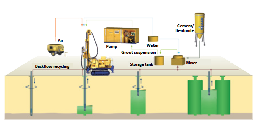
Jet Grouting
Jet grouting involves the mixing and partial replacement of the in-situ soil with cement slurry as opposed to conventional grouting which involves the injection of cement slurry into the voids in the soil. In its simplest form the process involves the ejection of cement slurry from a rotating grout tube, fitted with a nozzle, under very high pressure. The jet cuts a path outwards from the grout tube in a radial direction. The eroded soil is rearranged and mixed with the cement suspension. The combination of rotation and gradual stepwise withdrawal enables a large diameter in-situ grout column to be formed in the ground.
Applications of Jet Grouting
- Forming of grout columns to support structural loads
- Forming a contiguous wall for a caisson or cofferdam
- Forming a contiguous wall for lateral support
- Forming cut-off walls for groundwater control
- Forming a base seal to an excavation below the water-table
- Under-pinning of foundations and quay walls
- Sealing between piles on a contiguous pile wall construction
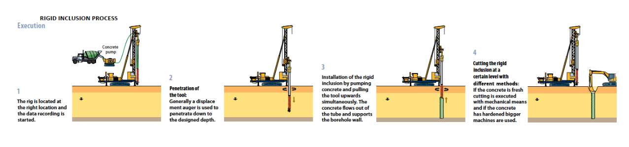
Rigid Inclusion
Rigid Inclusion or Controlled Stiffness Columns (CSC) can be installed through compressible soils to reduce settlement and increase bearing capacity. This technology economically combines the advantage ] of piles and shallow foundations. Loads are transferred through the high modulus concrete columns to a firm underlying layer. Based on the initial compressibility of the soil the distance between the rigid inclusion reinforcement elements is adapted depending on the allowable settlement of the structure.
This technique can be applied in all construction sectors, for houses, industrial and commercial buildings, embankments and under warehouse slabs, in the latter allowing the use of shallow foundations. Franki Africa offers rigid inclusion using the displacement auger or vibrated tube methods, either as part of a design and build package or as construct only to others’ design.
Applications of Rigid Inclusions
- Suitable for very weak, cohesive and organic soils.
- Settlements can be reduced by a factor 8 to 10 under high loads.
Foundation Types
Outline
As described in the previous section soil conditions vary significantly throughout South Africa. For this reason various types of foundations can be used to accommodate these conditions.
There are two basic categories of foundations:
- Shallow foundations, and
- Deep foundations
Shallow foundations transfer loads of the building to the soil at a point near the ground floor of the building and are usually classified as less than 1.500mm deep. Deep foundations transfer the load of the structure to the soil some distance below the ground floor of the building. Deep foundations are usually classified as being deeper than 3.000mm. The choice of foundation type is determined by the following:
- the total load of the building/structure
- ground conditions,
- economics,
- buildability, and
- durability
For example, strip footings are usually specified for residential buildings in which relatively small loads are carried mainly on external walls. Pad footings, piles or pile groups are more appropriate when the structural loads are more significant and carried by columns. If differential settlements must be tightly controlled, shallow strip or pad footings (except on rock or dense sand) will probably be inadequate so stiffer surface rafts or deeper foundations may have to be considered as alternatives.
Foundations can be classified in many ways; however the most common reference is in their form. There are five basic foundation types (forms).
- Strip (Mass concrete) foundations
- Raft or float foundations Pad or Isolated foundations
- Ground beams with column foundations
- Pile foundations
Strip foundations
Strip foundations which are also referred to as footings are used where light loads need support and are commonly used in the construction of residential buildings in South Africa. Any continuous strip foundation shall have a minimum thickness of 200 mm. However, the foundation depth will depend on:
- depth to a suitable stratum related to the required bearing load and width
- minimum depth requirements for frost, clay shrinkage or heave
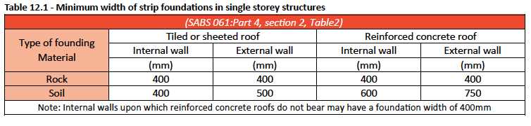
The minimum width of any continuous strip foundation shall not be less than 600 mm for a wall supporting a roof covered with concrete tiles, clay tiles or thatch; 400 mm for a wall supporting a roof covered with metal or fibre-cement sheets or metal roof tiles. For single storey structures strip foundations shall comply with SABS 0161: Part 4, section 2; see table 9.1
Note: The width of a strip foundation outside the scope of the table illustrated below and what is discussed here will depend on the inherent load-bearing capacity of the sub-soil and the loads from the building or structure as determined by a structural engineer.
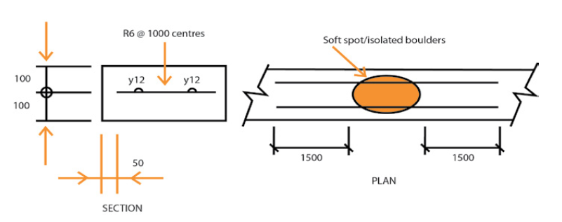
Foundation trenches can be stepped to accommodate sloping ground levels so that the required foundation depth is achieved.Where soft spots/isolated boulders do not exceed 1 500 mm in diameter, unreinforced strip foundations may be centrally reinforced with two No Y12 bars, extending a distance of not less than 1 500 mm beyond the face of such soft spots as shown in the following figure.
Where heavier loads are involved or where wet soil conditions are present the strip foundation can be reinforced to suit the bearing load and soil conditions as determined by a structural engineer. Strip foundations can be built to suit a number of variations as detailed below.
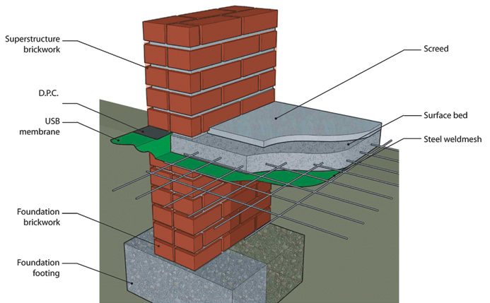
Figure 12.2 – 3D detail of a typical one brick wall
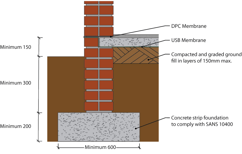
Figure 12.3 – Typical one brick wall strip footing (sectional views)
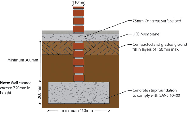
Figure 12.4 – Half brick wall internal foundation (110mm) non-load bearing.
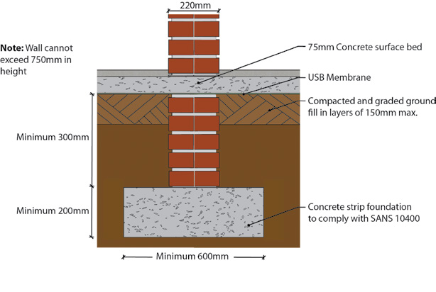
Figure 12.5 – One brick wall internal foundation
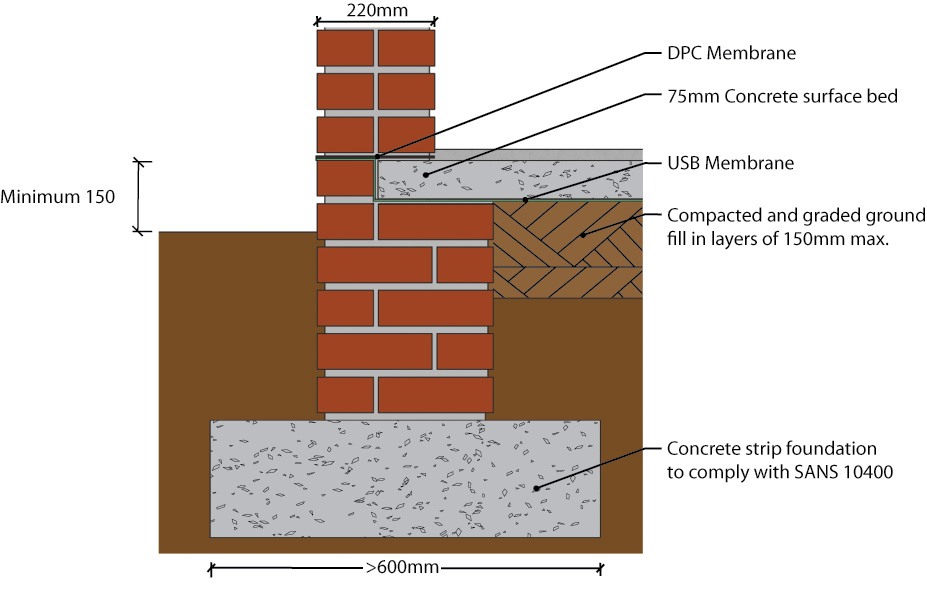
Figure 12.6 – One & Half brick wall foundation (340 mm with mortar joint)
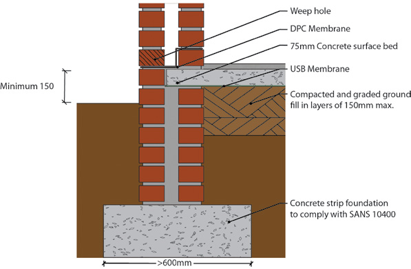
Figure 12.7 – Cavity wall foundation with weep holes
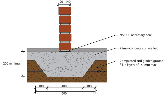
Figure 12.8 – Thickened surface bed foundation
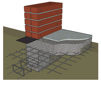
Figure 12.9 – 3D view of a typical raft foundation
Raft or Float Foundations
Raft foundations are used where the soil has a low bearing capacity and to reduce the effects of differential foundation movements as a result of variable soil conditions or variations in loading. Raft foundations generally have a larger surface area over which to spread the load and are generally used when the total area of pad foundations that would be required exceeds half the building area. Raft foundations can be stiffened with beams in order to help spread loading and stiff rafts are effective in reducing differential settlements. For residential buildings, rafts are generally used when construction is over expansive clay, made ground or fill and localised soft spots are anticipated. Raft foundations are also used effectively for buildings with basements.
A raft foundation generally consists of a reinforced concrete slab, whose thickness and stiffness are designed to spread the applied wall and column loads over a large area. For housing applications, rafts are often built with thickened perimeters, in which case they are effectively trench fill foundations with integral ground bearing floor slabs. Downstand edge beams also serve to stiffen the whole of the foundation structure. See Figure on next page. Piled raft foundations can also be used to limit settlements of more heavily loaded areas of the raft; where piles are tied into a stiff raft structure, which can mobilise the bearing capacity of both the surface soils and those at depth. Raft foundations need careful structural design and the services of a structural engineer would always be required when using raft foundations.
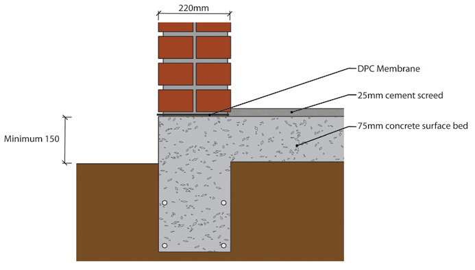
Figure 12.10 – Sectional view of a typical raft foundation
Pad or isolated foundations
Pad or isolated foundations are commonly used in portal frame construction and for columns in multi-storey structures where the building loads are carried by isolated columns rather than by load-bearing walls. As a rule-of-thumb this form of foundation tends to become more cost-effective whenever the distance between adjacent pads exceeds the dimensions of each pad. Panels of brick or block infill between the columns can then be supported either on ground beams spanning between pads or on separate footings, which may be at the same depth as the pads or shallower. (See Ground beams with column foundations.)
Pads may be circular, square or rectangular in plan and are usually formed using mass concrete of uniform thickness. However, where it is necessary to distribute the load from a heavily loaded column, the pad may be haunched as shown in the examples on the next page, and may require reinforcement. Where a deeper foundation is required to transfer the foundation loads to a stiffer or more stable stratum, the pad, together with the buried column that it supports, are referred to as a pier foundation.
Another variation of constructing foundations of this type, especially in marine conditions, is to sink a prefabricated concrete shell known as a caisson that can be sunk through ground or in water to install foundations or similar structures below the water line or water table. There are several caissons used in constructing foundations:
- Box caissons
- Open caissons, and
- Pneumatic caissons.
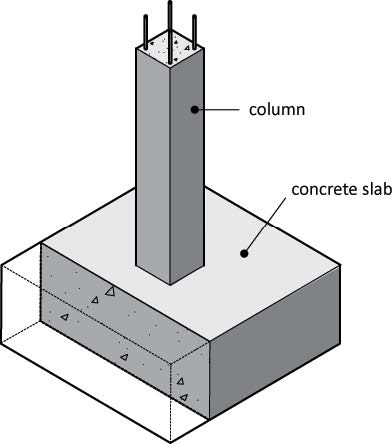
Figure 12.11 – Typical pad foundation
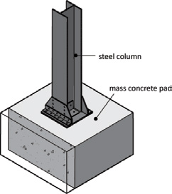
Figure 12.12 – Mass concrete pad for steel column
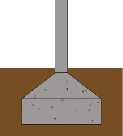
Figure 12.13 – Reinforced concrete pad with (haunched) sloping upper surface
Ground beams with column foundations
Ground beams usually consist of reinforced concrete sections, which may be cast-in-situ into excavated trenches or be precast with reinforcement loops at the ends for connecting to other beams in the foundations, providing a foundation for infill panels to be erected between columns, either in brick, block or curtain walling/shopfronts.
Reinforced ground beams in combination with concrete piles can be used for structural purposes to carry load bearing walls in multi storey buildings and would generally be used in coastal type projects where the soil conditions are not adequate to carry these types of loads.
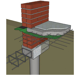
Figure 12.14 – Reinforced ground beam foundation on concrete piles
Pile foundations
Pile foundations are used where soil conditions are poor or the bearing capacity is very low. In most cases these poor soils overlay strong soils or rocks at depths where piles are driven down to levels where conditions are more suitable. Pile foundations are used in various situations where normal strip footings are inappropriate. Pile foundations generally are able to carry much heavier loads than other types of foundations and are often the most economic type of foundation when very heavy loads must be supported or uplift forces need to be resisted. There are basically two types of pile:
- end-bearing
- friction
End-bearing piles derive the greater part of their support from bearing forces at the base. They act basically as columns transferring loads through poor soil deposits, usually to dense granular soil or rock stratum at the foot of the pile. Friction piles, on the other hand, develop most of their support from friction between the shaft and the soil, usually firm clay. Both end-bearing and friction piles can be formed in a number of ways. The two main ones are:
- displacement piles
- non-displacement or replacement piles
Displacement piles (sometimes referred to as impact piles) are installed by forcing the soil out of the way as the pile is driven into the ground and they can be either preformed or cast-in-place.
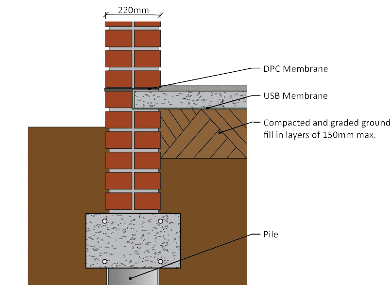
Figure 12.15 – Sectional view of reinforced ground beam foundation on concrete piles
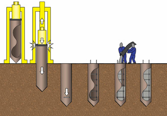
Figure 12.16 – Displacement piling
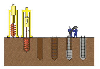
Figure 12.17 non-displacement piling
The main types include:
- all preformed piles of timber and reinforced concrete, continuous or jointed
- tubes and shells of steel or concrete, closed at the lower end, which are left in the ground after driving and then filled with concrete
- piles formed by driving steel tubes fitted with detachable shoes or temporarily closed at the bottom with plugs of concrete or gravel – the shoe is left behind or the plug hammered out as the tube is extracted while concrete poured through the tube runs out at the bottom to fill the void.
Non-displacement or replacement piles are formed by casting concrete or cement grout in a bored or excavated hole in the soil (sometimes referred to as augered piling). Non-displacement or replacement piles can be formed by:
- Driving an open tube, in sections if necessary, and extracting the soil core as the tube is sunk. When the bearing stratum is reached the tube is cleaned out. It is withdrawn as the concrete is poured or left as a permanent lining
- Augering a hole and filling it with concrete. A range of techniques is available for preventing collapse of the borehole and for placing the concrete.
Piles are usually drilled in clusters either two together, three in a triangular spacing or four and would be capped in these clusters (see Pile caps below) according to the design and structural requirements.
These clusters via the pile cap are then usually linked by ground beams to carry load bearing walls. See Figure 12.18.
Pile Caps
The upper end of a pile often needs to be adjusted on site so that an appropriate connection can be made to the remainder of the foundations. This adjustment normally takes place by means of trimming or by fitting an additional item of construction called a pile cap. Piles are often capped in groups; that is to say, connected in groups so that they act together rather than independently. See Figure 12.18.
It is very important to check that the pile cap reinforcement is properly connected with the projected starter bars of the pile itself, before the pile cap is cast.
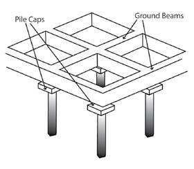
Figure 12.18 – Pile caps and ground beams
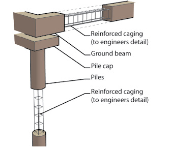
Figure 12.19 – 3D detail of reinforced ground beams and piles
Underpinning
In certain cases where there has been movement in an existing building this can be corrected by undercutting the foundation, casting a support beam in sections beneath the existing foundation, and then providing an excavated short pile beneath the support beam. The short pile is used as a support while a jack is applied to provide pressure between the support beam and the short pile.
Jacking continues until a specified pressure is achieved and the short pile has enough resistance to downward movement so the short pile and constructed beam can safely carry the load. The volume between the short pile and the support beam is then filled with concrete (and sometimes reinforced steel) and the jacks are removed
Lateral Support
The selection of a lateral support system requires careful consideration of all aspects of the proposed development, the site conditions and adjacent structures. In most cases, these factors cannot be considered in isolation and, together with economic considerations, interact to yield an optimal solution to the satisfaction of the full professional team. It is important that essential details of the proposed development be established at a fairly early stage in the project.
Such details include geometry, depth of excavation relative to rock-head (the upper surface of competent rock) and to the water table, proximity to site boundaries and adjacent structures, intended use of excavation, floor loading and permanence of lateral support. The systems of lateral support described below represent some of the options available to the designer:
Soil Nails
This system is an in-situ soil reinforcing technique used to stabilise slopes or excavations.
Post Stressed Anchors
Frequently used as tie backs to provide temporary or permanent lateral support to deep excavations, unstable slopes or similar.
Self Drilled Anchors
An innovative and versatile soil anchor solution in soft or very difficult ground conditions, where hole collapse renders conventional methods impractical.
Concrete Soldier Piles
Provide support either as cantilever walls, braced or tie-back walls, or to act as structural elements against which anchor forces are mobilised.
Contiguous and Secant Pile Walls
A row of concrete soldier piles installed to provide support either as cantilever walls or tie-back walls.
Diaphragm Walls
A reinforced concrete wall constructed in the ground using underslurry techniques, with widths of between 300mm and 1500mm and to depths of 60 meters.
Steel Sheet Piles
Easiest and quickest way to form a retaining wall, in soft or loose saturated soil profiles.
Pre-Cast Concrete Sheet Piles
Pre-cast concrete sheets interlock using the tongue and groove methodology. This is an alternative to steel sheet piles.
Pipe Jacking
Installation of concrete culverts and pipes up to 3 000 mm in size in almost any ground conditions. It entails manual excavation from within the protective confines of the jacking shield.
The jacking shield is jacked forward using high performance hydraulic jacks and once the shield has progressed far enough forward, a concrete pipe is then lowered into position behind the shield. Excavation and jacking continues until sufficient pipe sections have been installed.
Concrete
Outline
Concrete is a material made up of cement, water, sand (fine aggregate) and stone (coarse aggregate). The proportions of the materials of the concrete mix vary according to the strength and the way in which the concrete is transported, placed and compacted; not all concrete mixtures are the same.
Properties of concrete
When concrete is newly made, it is commonly referred to as fresh or plastic concrete. While in this fresh state, the shape of concrete can be changed and it can be compacted. Concrete remains in this plastic state for up to two to three hours. During this time, the mix of cement and water results in a chemical reaction, called hydration. Gradually the concrete hardens in a process of curing; a word used to describe concrete soon after it has set but is still weak is termed ‘green concrete’. The length of this period depends on a number of factors like the ambient temperature, cement type and water:cement ratio.
Mix requirements
The mix for a given strength of concrete can be specified in one of two ways. Proportions or quantities of each material to be used may be stated in terms of either volume or mass. Alternatively a strength requirement may be given. Specifying proportions by volume is done by describing a mix as 1:4:5, 1:3:3 etc., meaning a ratio of cement to sand to stone. For example 1:4:4 means one part cement to four parts sand to four parts stone.
Concrete mix proportions
| 1 | 4 | 4 |
| 1 volume | 4 volumes | 4 volumes |
| Cement | Sand | Stone |
On site, cement is usually measured in bags, and sand and stone in a builder’s wheelbarrow. The volume of a builder’s wheelbarrow is approximately equal to two bags of cement.
Note: The capacity of a builder’s type 5 wheelbarrow complying with SANS 795 is about 65 Litres.
Cement volume
A bag of cement contains 50 kg of cement. The volume of cement, when poured loosely into a container is approximately 33 Litres and it is recommended that only whole bags be used.
An example of a similar mix proportion by mass would be:
| Cement | 50kg |
| Sand | 200kg |
| Stone | 200kg |
If concrete is specified by strength, as it normally is; the concrete strength is measured in megapascal’s (MPa) which describes the pressure the concrete can withstand in a crushing test.
Concrete strength
Concrete strength is determined and specified by an Engineer, although there are three different general grades of concrete:
| Low Strength concrete | 5 MPa To 15 MPa | Suitable for unreinforced foundations (single storey); infill concrete in masonry (using 13.2mm stone only) and mass concrete. |
| Medium Strength concrete | 20 MPa To 40 MPa | Suitable for reinforced foundations; beams; slabs and floors; domestic driveways and footpaths. |
| High Strength concrete | >50 MPa | Suitable for reinforced high stress concrete members; precast items like railway sleepers, and heavy duty floors. |
Consistence
The consistence of the concrete mix must also be specified. The consistence affects how easily the concrete can be placed and compacted. Depending on where the concrete is to be placed and how it is to be compacted, concrete may range from stiff to sloppy or liquid, but still have the same strength if the mix is correctly proportioned. A slump test measures the consistence of the concrete mix and is used to control the amount of water in a mix. Remember by adding more water to the mix, not only weakens the concrete, but can also lead to segregation and grout loss which is one of the main causes of voids or honeycomb in concrete.
Hardening concrete
After a delay period, the concrete begins to stiffen. The rate of stiffening will depend on the cement type and content, temperature, humidity etc. Thereafter stiffening and hardening are due to the hydration process. Provided the concrete does not freeze and it does not dry, it will set, harden, and gain in strength.
Curing of concrete
The hydration reaction and the hardening of concrete is dependent on the presence of water. Strength gain is rapid during the early stages and provided sufficient water is always present, it will continue curing, though increasingly slowly, over a period of years. However, testing is usually done after a period of 28 days.
The earlier the concrete dries out, the lower the final strength will be. For proper strength gain to take place, the maintenance of proper temperature and moisture conditions to promote the continued hydration of the cement is vital.
The hotter it is the more quickly concrete gains strength. However, the curing temperature should never be above 80°C because this will result in a permanent loss of strength.
To promote curing, either cover the concrete with plastic sheeting that is held down firmly along its edges, or cover it with hessian or sacking that is kept wet. Curing should continue for at least seven days. Good curing also helps to limit cracking of the concrete.
Hydration:
Hydration occurs when cement and water are mixed together. The cement particles start to dissolve and this slowly produces fibres that grow from the cement particles into the water. These fibres interlock with other fibres from nearby cement particles, binding the mix together. This holds the concrete together and gives it strength. Heat is given off during this hydration process.
Bleeding and Settlement
Once fresh concrete has been placed, the heavy solid particles (cement and aggregate particles), which have a higher density than water, settle downwards, while the water migrates upwards. After a time, a film of water will be visible on the top of the concrete and this is known as bleeding. The most common causes of bleeding are due to excessive water content in the mix or a lack of fine material in the sand.
Water:cement ratio
Concrete strength is directly related to the water:cement ratio. The higher the water to cement ,the lower the strength and vice versa. The correct amount of water should be added to enable placing and compaction. Ant additional water will result in lower strengths and segregation. Typical water:cement ratios (w/c ratio), which are applicable and dependant on the strength requirement of the concrete range from 0.4 to 0.7.
Compaction
Compaction is the process of expelling air from the fresh concrete once it has been placed. Compaction is an important step in producing good concrete because voids in hardened concrete reduce the strength and durability. It is also very important to compact concrete thoroughly wherever concrete faces are to be exposed. Stiffer mixes and mixes with large sized aggregates require greater effort to compact; it is therefore important to use the correct size aggregates if detailed and specific off shutter finishes are required.
Cement
Outline
Cements are fine mineral powders. When these materials are mixed with water, they react chemically to form a strong rigid mass that binds aggregate particles together to make concrete. The cementitious materials dealt with in this section are all based on Portland cement and many contain a “cement extender.” This section gives information on the standards that apply in South Africa to cementitious materials for concrete; provides guidance on the selection of cementitious materials for various applications; and discusses, briefly, the manufacture and properties of cementitious materials and fillers.
Note: Masonry cements that comply with SANS 50413 are not included here because they are not intended for use in concrete. The national foreword of this standard reads: “This part of SANS 50413 gives the definition and composition of masonry cements as commonly used for brick-laying, blocklaying, for rendering and plastering only, and not for concrete. Users are therefore cautioned to use the cements only for their intended purpose.”
Standards
Cementitious materials for concrete, available in South Africa, include common cements and cement extenders. The applicable standards are:
Common cements
- SANS 50197-1 – Cement – Part 1: Composition, specifications and conformity criteria for common cements
- SANS 50197-2 – Cement – Part 2: Conformity evaluation.
Portland cement extenders
- SANS 55167-1 – Ground granulated blast furnace slag for use in concrete, mortar and grout Part 1: Definitions, specifications and conformity criteria.
- SANS 55167-2 – Ground granulated blast furnace slag for use in concrete, mortar and grout Part 2: Conformity evaluation
- SANS 50450-1 – Fly ash for concrete Part 1: Definition, specifications and conformity criteria.
- SANS 50450-2 – Fly ash for concrete Part 2: Conformity evaluation
- SANS 53263-1 – Silica fume for concrete Part 1: Definitions, requirements and conformity criteria
- SANS 53263-2 – Silica fume for concrete Part 2: Conformity evaluation These standards are discussed below.
SANS 50197-1
The standard specifies a number of properties and performance criteria. Composition and strength are required to be displayed by the manufacturer on the packaging of each cement produced.
Composition
The standard specifies composition of cements according to the proportion of constituents, i.e. Portland cement, extenders, and fillers.
The standard permits many different combinations of composition. In practice, however, the manufacturers are constrained by what is technically and economically feasible. The number of combinations that are currently being produced in South Africa is fewer than the number permitted by the standard. For the performance of a particular cement users should consult the relevant producer for these details.
Mechanical requirements
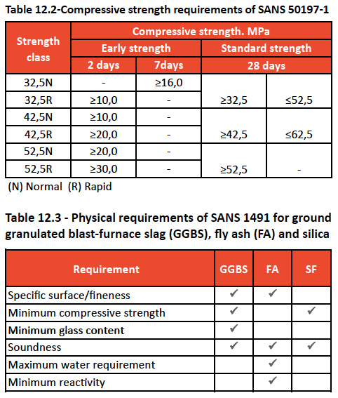
The standard specifies strengths, which are determined in accordance with SANS 50196-1 Methods of testing cement. Part 1: Determination of strength; using a water:cement ratio of 0,5. (The method is not the same as the cube test used for concrete.) Strengths are shown in Table 9.2 .
Note: that strengths must clear an early-age (2 or 7 days) “hurdle;” classes 32,5 and 42,5 must fall within a “window” at 28 days.
Other requirements
SANS 50197-1 lists other physical and chemical requirements with which cements must comply. These are monitored by the manufacturer and compliance is confirmed by external audit control sample testing. Details can be found in SANS 50197-2 – see table 12.3
SANS 1491: Parts 1, 2 and 3
This standard defines the specific material, states the chemical and physical requirements, and specifies packing and marking, inspection and methods of test. Physical requirements that apply are summarised in Table 12.3.
Composition of cement
Portland cement is the basis of all common cements covered by SANS 50197-1 and of site blends that include a cement extender.
The main raw materials used in the manufacture of Portland cement are limestone and shale, which are blended in specific proportions and fired at high temperatures to form cement clinker. A small quantity of gypsum is added to the cooled clinker, which is then ground to a fine powder – Portland cement.
When Portland cement is mixed with water to form a paste, hydration takes place. As a result, the paste gradually changes from a plastic state into a strong rigid solid. The hardened cement paste acts as a binder in concrete and mortar.
Hydration is an exothermic reaction, i.e. it provides heat. The hydration of Portland cement (PC) produces two main compounds:
- calcium silicate hydrate (CSH), and
- calcium hydroxide (lime)
CSH provides most of the strength and impermeability of the hardened cement paste. Lime does not contribute to strength but its presence helps to maintain, in the pore water, a pH of about 12,5, which helps to protect the reinforcing steel against corrosion.
Portland cement extenders and fillers
Portland cement extenders and fillers are materials used with Portland cement, and must never be used on their own. The main reasons for the widespread use of Portland cement extenders are:
- Cost saving – extenders are generally cheaper than Portland cement.
- Technical benefits – extenders improve impermeability and durability of the hardened concrete; some extenders improve the properties of concrete in the fresh state.
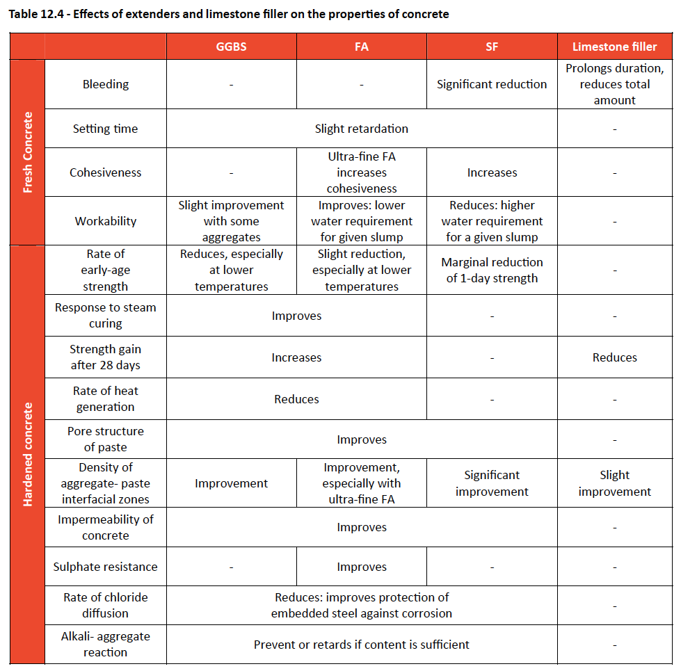
The Portland cement extenders discussed below differ from each other. These differences affect the rate of early-age strength gain, causes the “fine-filler” effect, and affect the rate of heat development due to cementing reactions. Substituting a cement extender for part of the Portland cement reduces the rate of strength gain at early ages in a given concrete. The extent of the reduction increases with increasing substitution level.
Extremely fine extender particles act as nuclei for the formation of calcium silicate hydrate, which would otherwise form only on the cement grains. This fine-filler effect brings about a denser and more homogeneous microstructure of the hardened cement paste and the aggregate-paste interfacial zones, resulting in improved strength and impermeability. The extent of the fine-filler effect depends on the content of extremely fine particles in the extender.Fine particles of filler materials, e.g. limestone, can also exhibit the fine-filler effect.
Concrete in which part of the Portland cement is replaced by an extender produces heat at a rate
slower than that of a similar concrete made with Portland cement only. The slower the rate of heat development, the lower the temperature rise and therefore the smaller the likelihood of thermal cracking. The manufacture and mechanism of action of Portland cement extenders and limestone filler in concrete are discussed below.
The effects of these materials on the properties of concrete are summarised in Table 9.4. Effects tend to increase with increased level of substitution. Improvements to the properties of hardened concrete, brought about by the use of extenders, can be realised only if the concrete is properly cured.
Ground granulated blast-furnace slag
Ground granulated blast-furnace slag (GGBS) is a by-product of the iron-making process. The hot slag is rapidly chilled or quenched (causing it to become glassy) and ground to a fine powder.
When mixed with water, GGBS hydrates to form cementing compounds consisting of calcium silicate hydrate. The rate of this hydration process is however too slow for practical construction work unless activated by an alkaline (high pH) environment.
When Portland cement and water are mixed, the pH of the water rapidly increases to about 12,5 which is sufficient to activate the hydration of GGBS. Even when activated by Portland cement, GGBS hydrates more slowly than PC.
The effect of GGBS on the properties of concrete depends on the properties of the Portland cement, the GGBS content of the cementitious material and the fineness of the GGBS.
Fly ash
Fly ash (FA) is collected from the exhaust flow of furnaces burning finely ground coal. The finer fractions are used as a cement extender.
Ultra-fine FA is sold as a separate product. FA reacts with calcium hydroxide, in the presence of water, to form cementing compounds consisting of calcium silicate hydrate. This reaction is called pozzolanic and FA may be described as a synthetic pozzolan.
The hydration of Portland cement produces significant amounts of calcium hydroxide, which does not contribute to the strength of the hardened cement paste. The combination of FA and PC is a practical means of using FA and converting calcium hydroxide to a cementing compound.
Silica fume
Silica fume (SF) is the condensed vapour by-product of the ferro-silicon smelting process.
SF reacts with calcium hydroxide, in the presence of water, to form cementing compounds consisting of calcium silicate hydrate. This reaction is called pozzolanic and SF may be described as a synthetic pozzolan. Because the hydration of PC produces calcium hydroxide, the combination of SF and PC is a practical means of using SF and improving the cementing efficiency of PC.
In addition to the chemical role of SF, it is also an effective “fine filler.” The extremely small SF particles in the mixing water act as nuclei for the formation of calcium silicate hydrate which would otherwise form only on the cement grains. SF will also change the microstructure of the interfacial zone. The result is a more homogeneous microstructure that has greater strength and lower permeability. (To ensure thorough dispersion and effective use of the SF, the use of plasticising admixtures is recommended.).
Limestone filler
This is limestone, finely ground but not chemically processed. When mixed with Portland cement and water, finely ground limestone is chemically virtually inert (although there may be some minor reactions). Depending on its fineness, limestone may however act as a “fine filler” in fresh paste.
Limestone may be used as a filler in common cement or as a workability improver in masonry cement. The effect of limestone on the properties of concrete or mortar depends on the specific limestone, whether a grinding aid is used in production, and the fineness of the limestone.
Note: The limestone (CaCO3) used in cements complying with SANS 50197-1 is not to be confused with:
- Building lime (hydrated or slaked lime Ca(OH)2) which is used in mortars and plasters.
- Road lime (also hydrated or slaked lime Ca(OH)2) which is used in road material stabilisation or modification.
- Quick lime (CaO) which is highly aggressive and is used in the metallurgical industry.
- Agricultural lime which, although chemically similar to the limestone used for cement, has less stringent compositional requirements.
There is no Ca(OH)2 or CaO used in cements complying with SANS 50197-1. See Table 12.4
Selection
Cementitious materials used for concrete may be:
- A common cement on its own.
- A site blend of a common cement and a cement extender, combined in the concrete mixer while the concrete is being mixed. Extenders must comply with SANS 55167 – 1 and 2 and must not be used without Portland cement.
Common cements are manufactured in five categories according to composition, designated CEM I to CEM V. CEM I consists essentially of Portland cement on its own, while CEM II to CEM V are factory blends of Portland cement and cement extenders, like (GGBS), (FA) and (SF) or fillers, as described above under composition.
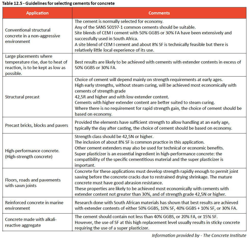
It should also be noted that generally as the extender content of a cement increases, the rate of compressive strength development at early ages is reduced. Table 12.5 gives guidelines for selecting cement type for various applications.Unless stated otherwise, the strength class of the common cement may be 32,5N or higher. See Table 12.5
Storing and handling cement
Storing and handling of cement on site should be carefully controlled to minimize wastage and to ensure that you get what you want in terms of quality and quantity. Cement may be delivered to site either in bags or in bulk.
Storing of bagged cement should follow the principle of first in, first out; the strength of cement weakens with age. The following tips should be remembered when storing bagged cement:
- The cement store must be weatherproof
- The store should have a damp-proof floor
- Bags should be closely stacked to reduce air circulation between bags
- Different types of cement must be stored separately
- Bags must be carried and not dragged
When receiving bagged cement deliveries, the bags should not be accepted if they are broken or wet. Bulk silos can also be used for the storage of cement on site; with the cement delivered to site by bulk transporters. The silos have a capacity of between 12-50 tons. Some manufactures provide mini-silos for smaller type projects e.g. residential buildings.
Cement in bulk does have certain advantages over those in bags:
- Bulk cement is usually cheaper per KG
- Storage is easier
- Wastage from broken bags in reduced
- Handling costs are reduced
When cement is delivered in bulk, check the seals on the tanker to ensure they have not been broken or tampered with. Always remember to lock the hatches of bulk silos daily.
Aggregates
Definition
Aggregates can be defined as any granular material used as the main constituent of concrete, mortar, or plaster. Aggregate is described by its size – as course, fine; or all-in; or its source. 19mm stone and riversand or crusher sand are the most commonly used aggregates in manufacturing normal concrete. Aggregates are used to reduce the cost per cubic metre of concrete and reduce shrinkage and other deformations.
Shape of aggregate
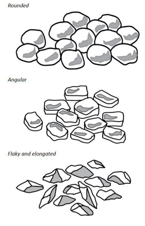
In order to get strong concrete, the aggregate should be well placed and packed closely together . The shape of the crushed aggregates ranges from rounded; angular; flaky; and elongated. Flaky and elongated aggregates should be avoided in concrete mixes. Aggregates obtained from riverbanks, dunes and pits are usually better shaped than crushed material. Rounded aggregates make a mix more workable and require less water and less cement, but give lower strengths. Long, flat, sharp, and badly shaped particles make harsh ‘unfriendly’ concrete and contribute to poor workability.
Types of aggregate
Coarse aggregate (Stone)
Coarse aggregate is used in concrete for bulk and because it is cheaper than cement, making the mix more economical. If the stone size is increased, less water is needed to give the required slump, therefore less cement is necessary to maintain the same water:cement ratio and strength. There are a number of different sizes of stone, the four commonly used nominal sizes are; 26.5mm; 19mm, 13.2mm and 9.5mm. Stone is sorted by using a sieve or screens with the relevant size holes in order that the stone to be sized.
Fine aggregate (Sand)
Fine aggregate is used as a void filler. It fills up spaces between the stone and cement paste. It also affects the amount of water needed in the mix and as described above the shape of the particles is also important as it affects the amount of water required and the slump. Sand also reduces the paste content and makes the concrete more stable. Sands lacking fine fractions (fines) – passing through a 300μm sieve -produce harsh concrete that bleeds and has a tendency to segregate. An essential requirement is that sand should be free of organic matter such as roots, twigs, humus, clay etc.
Water requirements
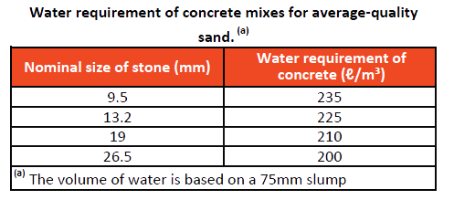
Only clean fresh water, free from vegetable or organic matter, earth, clay acid or alkaline substances in either suspension or solution should be used. Depending on the size of stone used in the mix, the amount of water required per m³ can be estimated in the following way:
For example if you are using a 19mm stone, the water required in the mix would be about 190ℓ for every cubic metre.
Manufacturing Concrete
Composition of concrete mix
The composition of a good quality concrete mix consists of cement, sand, stone, and water as a lubricant, proportioned together to produce concrete which will satisfy the specific performance requirements (workability, compressive strength, and durability) as well as to give the correct yield or blend.
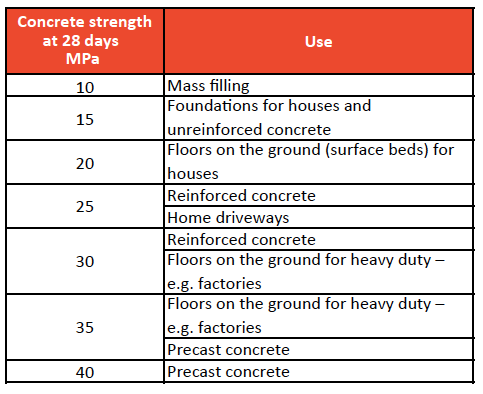
Classification and uses
A concrete mix ratio as well as the size of the course aggregate determines the strength of the concrete for a specific concrete element or component. Various recommended concrete strengths for various uses are however provided as guidelines in the following table.
Mix proportions and quantities
The materials in concrete, i.e. cement, course and fine aggregate, water and admixture (if required), should be proportioned to give the required properties in the fresh and hardened state.
As described above, mix requirements for a given strength of concrete can be specified in one of two ways. Proportions or quantities of each material to be used may be stated in terms of either volume or mass. Alternatively a strength requirement may be given.
Mix proportions in the table overleaf are based on the assumption that a CEM II/A 32.5 cement will be used. CEM I 42.5 or higher cements will give a stronger concrete but may be less economical. Cements with higher extender contents (e.g. CEM II/B or CEM III) will develop strength more slowly and will require particular care with curing.
The amount of water required is not given in the table (see selection of water:cement ratio that follows this table). The mix should contain enough water to achieve the required consistence. Consistence may be assessed by eye or measured by carrying out the slump test (SANS Method 5862-1:2006). Recommended slumps are:
- 50–100 mm for compaction by mechanical vibration
- 100–150 mm for compaction by hand
A mix made according to this table, and to the required consistence, should be assessed for stone content before being used on a large scale. This can be done by compacting some of the concrete in a container, e.g. a bucket, by the means (vibration or hand tamping) to be used on the job. If stones protrude from the surface, stone content is too high. If not, scratch the surface of the compacted concrete (before it hardens) with a nail or screwdriver. If the stone content is right, stones should be found two or three millimetres below the surface. If they are deeper than this, the stone content is too low.
If stone content is too high, reduce it by 10 % and increase sand content by the same amount, i.e. volume or mass. Then reassess. If stone content is too low, increase it by 10 % and reduce sand content by the same amount, i.e. volume or mass. Then reassess. The mix proportions given in table 12.6 are conservative. If the quantity of concrete to be made exceeds about 100 m³, it is probably possible to save costs by selecting materials and having a mix designed.
Concrete mix design (rules)
(In accordance with “Mix Proportions & Quantities” table 12.6 on the following page)
- The volume of the concrete is the sum of the solid volumes of the constituents; which implies that the concrete is fully compacted, i.e. it contains no air voids.
- For any specific materials and conditions of test, the strength of fully compacted concrete depends only on the ratio of water to cement (w:c) in the mix. The relationship between the type of cement used and the ratio of water to cement will have a significant effect on the strength characteristics of the concrete mix.
- For a given consistence and with given materials, the total amount of water required per unit volume of concrete (the amount of water required) is practically constant regardless of cement content, water:cement ratio, or proportions of aggregate and cement.
The water requirement of a concrete mix at a given consistence (slump) is determined mainly by two factors: the properties of the sand, i.e. particle shape, surface texture and grading, and the nominal size of the stone.
Selection of water:cement ratio
The water to cement ratio is determined by specifying the type of cement to be used to the strength requirement of the mix. To select the appropriate water:cement ratio to achieve a required characteristic strength, the following guidelines are provided (see table 12.7); for example, concrete with a required strength of 20MPa will need a w/c of 0.66, if mad with a CEM 32,5 common cement. The amount of water to the amount of cement plays an important role in its strength characteristics. The more cement, the stronger the paste, resulting in stronger concrete. The less cement, the more watery the paste will be, resulting in a weaker concrete. See Table 12.7
Admixtures
Admixtures are chemicals other than water, cement, or aggregates, which are added to concrete at the mixing stage to modify some of the properties of the mix. Admixtures should never be regarded as a substitute for good mix design, good workmanship, or use of good materials. Only admixtures complying with the requirements of SANS 50934 1-6 should be used.
The most common reasons for using admixtures in concrete are:
- To increase workability without changing water content.
- To reduce water content without changing workability.
- To effect a combination of the above.
- To adjust setting time.
- To reduce segregation and/or bleeding.
- To improve pumpability.
- To accelerate the rate of strength development at early ages.
- To increase strength.
- To improve potential durability and reduce permeability.
- To reduce the total cost of the materials used in the concrete.
- To compensate for poor aggregate properties.
Admixtures are generally classified according to their functions; the most common being:
- Plasticizers or water reducing agents (WRA)
- Superplasticizers or high range water reducers (HRWR)
- Retarders
- Accelerators
- Air-entraining agents (AEA)
Plasticizers
When added to a concrete mix, plasticizers (water-reducing agents) are absorbed on the surface of the binder particles, causing them to repel each other and deflocculate. This results in improved workability and provides a more even distribution of the binder particles through the mix. The main types of plasticizers are lignosulphonic acids and their salts, hydroxylated carboxylic acids and their salts, and modifications of both.
Uses
- Plasticizers usually increase the slump of concrete with a given water content.
- Plasticizers can reduce the water requirement of a concrete mix for a given workability, as a rule-of thumb, by about 10%.
- The addition of a plasticizer makes it possible to achieve a given strength with a lower cement content.
- Plasticizers may improve pumpability.
Superplasticizers
These admixtures are chemically distinct from normal plasticizers and although their action is basically the same, it is more marked. When they are used to produce flowing concrete a rapid loss of workability can be expected and therefore they should be added just prior to placing.
Superplasticizers form an important ingredient of highstrength concrete. Superplasticizers are usually chemical compounds such as sulphonated melamine formaldehyde, sulphonated naphthalene formaldehyde, and modified lignosulphonates.
Uses
Superplasticizers are used to best advantage:
- In areas of congested reinforcement.
- Where a self-levelling consistence facilitates placing.
- For high-strength concretes by decreasing the water:cement ratio as a result of reducing the water content by 15–25%.
Retarders
These admixtures slow the chemical reaction of the cement and water leading to longer setting times and slower initial strength gain. The most common retarders are hydroxylated carboxylic acids, borax, lignins, sugar and some phosphates.
Uses
- When placing concrete in hot weather, particularly when the concrete is pumped.
- To prevent cold joints due to duration of placing.
- In concrete which has to be transported for a long time.
Accelerators
These admixtures speed up the chemical reaction of the cement and water and so accelerate the rate of hardening and/or early gain in strength of concrete. They do not significantly affect the setting time. Among the main types of accelerators are calcium chloride, calcium formate, soda ash, potassium chloride and a number of organic materials. Calcium chloride appears to be the only one that is reasonably predictable in its performance, but it tends to promote corrosion of steel in concrete.
Uses
- Where rapid setting and high early strengths are required (e.g. in shaft sinking).
- Where rapid turnover of moulds or formwork is required.
- Where concreting takes place under very cold conditions.
Air-entraining agents
An air-entraining agent introduces or traps countless very small separate air bubbles in the concrete mix to improve workability and reduce bleeding of fresh concrete and enhance durability of hardened concrete exposed to cycles of freezing and thawing. Entrained air tends to reduce strength and for that reason mix proportions (water:cement ratio) should be revised accordingly.
The main types include salts of wood resins, animal or vegetable fats and oils and sulphonated hydrocarbons.
Uses
- Where improved resistance of hardened concrete to damage from freezing and thawing is required.
- For improved workability, especially in harsh or lean mixes.
- To reduce bleeding and segregation, especially when a mix lacks fines.
Dosage and dispensing
The correct dosage of admixture is crucial for satisfactory mix performance and the proper use of well-maintained and calibrated dispensing equipment is essential.
Admixture suppliers normally provide, install and service dispensers which are either manual or automatic. Admixtures should be added to a concrete during mixing with the last portion of the mix water in order to ensure even dispersion of the admixture throughout the concrete, unless delayed addition is necessary for a specific purpose. The admixture should not be added directly to the dry cement or aggregates.
For the majority of admixtures it is not necessary to change the concrete mixing procedure. Any special requirements will be given in the admixture manufacturer’s product literature.
Mixing of concrete
Concrete can be produced by either batching or mixing on site or by purchasing ready-mixed concrete. The choice depends on a number of factors:
- Materials properly specified and in sufficient volumes.
- Plant available (mixer, storage, dumper etc.) does it need to be hired or purchased – at what cost.
- Labour
- Whether space on site allows for batching and mixing.
- Technical expertise
- Quality control, mix designs and calibration
Site mixingWhenever the concrete constituents are mixed by hand on site, it should be done on a proper wooden platform, not on a flat concrete surface area. A dry concrete surface area tends to absorb a lot of water from the mix design which will have an impact on the water:cement (w:c) ratio.
Measuring quantities on site for a particular concrete batch may be done by means of the volumetric method or by weight batching. When using the volumetric method it is important that the item being used in measuring the volume be used throughout the mixing process and that an identical backup item is available should the one being used be damaged or misplaced.
Making use of a concrete mixer is always recommended; it reduces production costs, improves consistency, and provides for more reliable mixing.
Ready mixed concrete
When using ready mixed concrete it is advisable to order concrete well in advance especially if dealing with large quantities. It is also important that your quantities have been accurately estimated; it is costly to order small quantities when you have under estimated and also costly when you overestimate quantities and end up with waste.
Transportation and placing of concrete
The way concrete is transported is very important; be it with a dumper, sliding chute, pumping, crane skip or wheelbarrow. During the transportation and the placing of concrete, the following points need to be considered and taken into account:
- The mix should not dry-out
- Segregation of materials in the mix must be avoided
- As soon as the concrete is placed the concrete must be properly compacted in its final position
Drying out
Where the possibility exists that there will be a delay between mixing and the placing of the mixed concrete, especially in hot weather, the quantity of water and hence the water:cement ratio must be increased to compensate for this drying out process. Sufficient protection should also be provided to minimize evaporation during transportation. During wet rainy seasons, the concrete should be covered when being transported to avoid too much water being added to the mix.
Note: The retempering of a dried out mix (adding of extra water to and re-mixing concrete) must under no circumstances be allowed.
Segregation of materialsIf concrete is allowed to segregate when being transported, the mixture will not be uniform when placed. Some areas will have a high paste like content, while others will be very stony. If there is insufficient paste, the concrete will be honeycombed, which will result in a poor quality mix and weak concrete. To improve cohesiveness or reduce segregation, one or more of the following steps can be taken:
- Use less water (i.e. use a lower slump concrete)
- Use less stone
- Use smaller size stone
- Use more fine materials (the use of a fine blending sand is preferable to increasing the amount of original sand)
Compaction
Compactability is the ease with which entrapped air can be expelled. Air is sometimes trapped in concrete when it is placed and must be expelled if maximum density is required. 1% of entrapped air in a concrete mix can cause up to a 5% loss in compressive strength.
To ensure that a proper density is maintained when placing concrete, vibrators are used to bring the air bubbles to the surface and expel them as such. Over vibration again may lead to segregation of the concrete mix, and needs to be well supervised.
Mobility
Mobility is the ease with which concrete will flow around obstructions, such as reinforcement, and into corners of formwork. Highly mobile mixes are required in heavily reinforced or irregularly shaped sections.
Concrete Tests
Workability
The term workability is used to describe the ease with which operations such as placing concrete can be carried out. Even a stiff concrete can be workable when sufficient compaction energy is applied to the concrete. Unfortunately, workability cannot be measured directly. Workability comprises several properties, the more important ones being:
- Consistence
- Cohesiveness
- Mobility
- Compactability
The workability of a concrete mix can be affected by balancing the following factors:
- Stone size – smaller stone improves the workability but increases the cost for a given strength.
- Fines content of sand – a lower fines content increases the cohesiveness of the concrete while too much fines tends to make concrete “sticky”. The word fines relates to the very small sand particles (passing a 0.075mm or 75μm sieve)
- Cement content – high cement contents makes for sticky mixes
- Stone content – the higher the amount of stone in the mix, the harsher and more difficult it is to compact. When using too little stone, the mix becomes uneconomical because more cement is used.
Consistence refers to the stiffness or sloppiness of fresh concrete and is most commonly measured by a slump test. Concretes of the same consistence may differ in workability. A slump test measures the consistence of the mix and is used to control the amount of water in a mix. The sloppier the concrete the greater (higher) the slump. The test must be carried out in accordance with SABS Method 5862-1:2006.
The slump test
Materials and tools required
- A sample of freshly mixed concrete (about half a wheelbarrow full)
- A wheelbarrow and shovel
- A non-absorbent rigid surface, e.g. a flat steel plate about 600 x 600‑mm by 3‑mm thick
- A metric rule or tape measure
- A scoop
- A steel tamping rod, 16‑mm in diameter by 600‑mm long –one or both ends must be rounded
- A spirit level (optional)
- A standard slump mould. The footplates should be positioned 5 mm above the base of the cone.
How to measure the slump
- Mix the concrete in the wheelbarrow.
- Wipe all the tools with a damp cloth.
- Put the steel plate down on a level place so that it is firm, and then put the slump mould on it with the narrow end at the top. Stand on the foot-pieces.
- Fill the slump mould in three layers of about equal depth. Tamp through each layer 25 times with the rounded end of the tamping rod.
- The last layer should more than fill the mould. After tamping the last layer, strike off the excess concrete, using a sawing and rolling motion of the tamping rod, so that the mould is completely filled and level.
- Hold the mould by the handles to keep it steady while you step off the foot-pieces.
- Slowly and steadily remove the slump mould by raising it vertically; take a few seconds to do this (5 -10 seconds)
- Turn the slump mould upside down and place it on the plate, next to the concrete.
- Rest the tamping rod or a spirit level on top of the slump mould so that one end is above the concrete.
- Carefully measure the distance between the bottom of the tamping rod or spirit level and the highest point of the concrete to the nearest 5‑mm (see Figure 12.20 below)
- If you don’t get a normal slump, repeat the test. If the slump is still not normal, ask for advice – see types of slump in Figure 12.21.
Note: The slump is the height from the bottom of the rod or the spirit level to the highest point of the concrete specimen.
When you measure the slump, record the following information:
- Date and time
- Place of test
- Name of tester
- Sample number
- Type of test
Concrete normally has a slump value specified. The concrete is acceptable provided the measured slump is within 25mm or one third of the specified value, whichever is the greatest.As an example, if the specified slump is 75mm, the actual test results should be between 50-100mm. This figure is obtained by subtracting 25mm (75 x⅓) from 75mm and adding 25mm to 75mm. The greater value of 25mm or ⅓ of the specified slump is to be used. A further example to demonstrate this calculation with a higher slump is: A slump of 100mm is therefore calculated as – 100mm x 0.333 (⅓) which is greater than 25mm. In other words, the limits for a 100mm slump must be:
Upper: 100mm + 33 = 133mm
Lower: 100mm – 33 = 67mm
Figure 12.20 – Slump test basics
Figure 12.21 – Types of slump
Compressive strength
Compressive strength is usually considered to be the most important property of hardened concrete. Compressive strength is the resistance of standard, plane-ended specimens of concrete to crushing. Strength is expressed as a stress which is force per unit area on which the force acts, i.e. strength = F/A.
Notwithstanding all means of quality control, it sometimes happens that the concrete still does not meet the required quality. To eliminate this factor as far as possible test cubes are taken. The tests done will depend on the nature of the project. In large contract works a sample is usually taken from every 100 m³ of concrete made. And for smaller jobs, a sample is taken for every different part of the work done.
Note:Three cubes are needed for each test. If they are to be tested at 7 days and at 28 days, you will need six cubes – three for each test.
When sampling from a ready-mix truck, the concrete must be divided into equal parts (usually about four) and a sample taken from each part. Don’t take a sample from the first or last part of the mix being offloaded.
Likewise when taking samples from a freshly made site mix, distribute the heap into four equal parts and follow the same procedure by taking samples from each part for the cube test.
Material and tools required:
- A sample of the concrete (about half a wheelbarrow full)
- A wheelbarrow and a shovel
- A scoop
- Three standard moulds for each test
- A steel tamping rod, 600‑mm long with a diameter of 16‑mm that has at least one end rounded
- A steel float
- Pieces of writing paper (absorbent paper) for labels
- A ballpoint pen or, preferably, a soft pencil
- Mould release oil
- Grease
How to make the cubes
- Check that:
- moulds are clean and do not have dust or dirt on them,
- the joint faces have been greased,
- they are assembled in the right way,
- the bolts are tight
- Smear release oil very thinly on the inside faces of the moulds.
- Place the moulds on a firm, level surface.
- Mix the concrete well in the wheelbarrow.
- Fill the moulds with concrete in 50 mm layers.
- Tamp each layer at least 45 times with the rounded end of the tamping rod to get the air bubbles out.
- The last layer should more than fill the mould. After tamping the last layer, use the steel float to strike off the surface of the concrete so that it is level with the top of the mould.
- Write the following on a label for each cube:
- the company’s name,
- the contract number or the reference number,
- the date when the cube is made
- Gently press the label onto the top of the cube.
- Cover the cube with damp sacking followed by a sheet of plastic and store it in the shade, away from wind and where it will not be disturbed.
- If the weather is cold, make and store the cubes indoors.
The next day
- Loosen all the bolts on the mould.
- Gently loosen the sides of the mould and remove them.
- It is a good idea to write the information on the label on the cube with a lumber crayon.
- Put the cubes into water. The temperature of the water should be 22°C–25°C.
- Leave the cubes covered with water until they are taken to the testing laboratory.
- Clean the moulds and assemble them again.
Figure 12.22 – Test cube basics
Reinforced Concrete
Steel reinforcement in concrete
Reinforced concrete has steel reinforcing added in addition to the plain concrete mass. Steel or reinforcing steel is strong in tension. The combination of the compressive strength of concrete and the tensile strength of steel reinforcing increases the ability of a concrete element or member or members to carry additional loads.
Two types of steel are generally used as reinforcement in concrete; mild steel (R-bars) and high yield steel (Y-bars). The diameters can vary from 8mm to 40mm. The distinctive feature between the two types is that Y bars have longitudinal or transverse ribs on the bar for a better bond which is often referred to as deformed bars.
Mild steel (plain round steel bars)
Mild steel bars are suitable for most forms or reinforced concrete and can be easily bent, cut and welded. They are denoted with a prefix (R) to indicate a mild steel bar with typical diameters ranging from 8-40mm.
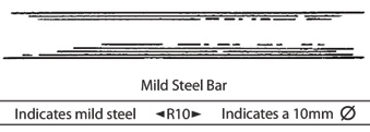
Bars 16mm and larger in diameter are used for reinforcing foundations, retaining walls and beams. Smaller bars are used for floor and roof slabs- (which can also be in the form of weld-mesh reinforcing –see weld-mesh reinforcing below). In most cases, 8-12mm bars are used as stirrups and column links. Mild steel bars have a characteristic strength of approximately 230MPa.
High yield stress deformed bars
Deformed bars have a characteristic tensile strength of at least 450MPa. They can be identified by the ribs running around the bar, compared with the smooth surface of mild steel bars. The ribs formed on the surface differ from manufacturer to manufacturer, and are used to increase the bond between the steel and the concrete. Structures requiring high concrete strength, like multi-story buildings, will usually specify high yield deformed bars.
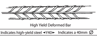
They are available in the same diameters as that of mild steel and are denoted with the prefix (Y).
Welded Mesh Reinforcing
Welded mesh reinforcing is a convenient and cost effective alternative to conventional bar reinforcement (rebar) for the following reasons:
- The mesh is generally specified and manufactured according to standard references making for easy site identification, quality control and management.
- The mesh is manufactured in sheets or rolls resulting in a quick and simple site installation process.
- Although generally used in surface beds (concrete floor slabs on fill) and concrete roads, mesh can also be used in suspended floor slabs, concrete walls, culverts / drains and composite brick / concrete retaining walls.
How reinforcement is used
Reinforcement in concrete is used to control bending, shear or compression.
Bending
Structural members such as beams and slabs are subjected to bending. When a beam or slab, which is supported at its ends, is loaded in the middle, it will tend to sag or bend toward the middle. This causes compression at the top and tension at the bottom. If the loading is continued, the beam will start cracking (at the bottom) and will eventually fail (break). Such failure can be prevented by inserting reinforcing steel bars near the bottom face, in order to strengthen the beam to carry more loads.
Shear
A simply supported beam (supported at its ends only) does not only bend but also has a tendency to move downwards or shear at the supports, resulting in cracks. This is prevented by using inclined bars or vertical stirrups as reinforcement.
Compression
Very tall buildings have high compressive forces transmitted through their structure, especially in the columns. To strengthen these columns and to help carry some of these compressive forces, reinforcement is used. Compression bars are also used on highly stressed simply supported beams as top steel.
Although Y bars have ridges that bind it mechanically to the concrete with friction, it can still be pulled out of the concrete under high stresses, an occurrence that often precedes a larger-scale collapse of the structure. To prevent such failure, bars are either deeply embedded into adjacent structural members, or bent and hooked at the ends to lock it around the concrete and other reinforcing bars. This first approach increases the friction locking the bar into place while the second makes use of the high compressive strength of concrete.
A structural engineer or technician is usually asked to design reinforcing steel to carry loads of a building or individual structural members or elements. The calculations are based on the recommendations prescribed in the code of practice for the structural use of concrete – SABS 0100 1:1992 as amended April 1994. This code identifies formulae that enable the designer to determine bending moments, shear forces, the area and weight of steel required.
Steel reinforcement concrete cover
Unless otherwise stated to cover steel reinforcement in concrete, the concrete cover shall be as follows:
| Foundations | not to be less than 75mm |
| Columns | not to be less than 40mm |
| Beams | >not to be less than 25mm |
| Slabs | not to be less than 12mm |
Pre-concreting checklist
- Check inherent rigidity of the cage and or mat
- Check correct numbers of bars have been fixed
- Check adequate provision of continuity reinforcement or connection to previous starter bars
- Check that starter bars, starter boxes, void formers, fixing etc. are present and in correct locations
- Check correct use of adequate cover blocks, reinforcement spacers, etc. to prevent cage movement during concreting
- Check cover to reinforcement is correct at all locations
- Ensure adequate access for concrete compaction (e.g. by poker vibrator)
- Ensure that harmful chemicals have not been used anywhere
The Foundation Process
Setting out
With pegs and string, carefully measure out the size of the building or foundation slab, putting a peg in the ground on each one of the corners; For example, shown in Figure 12.23, on the four corners. To get the first corner in a building square, put a peg in the ground and attach a piece of string. Stretch the string in a straight line, running parallel to the building line, for 3 metres. Put another peg in the ground at 3 metres and attach the string. Then attach another piece of string to the first peg and stretch it 4 metres. When the diagonal measurement between the 3 metre peg and the 4 metre peg is 5 metres, you have a square corner to start from. (This is known as the 3,4,5 method). See Figure 12.24.
As soon as this square corner or 90 degree angle is obtained, other measurements can be taken from any of these lines to set out the building.
Another way of making sure that a rectangular building is square is to take a diagonal measurement across the building, from one corner to the other, and then take another measurement between the other two corners, forming a cross. If these measurements are not the same, you will need to recheck the side measurements. When these measurements are the same, your building is square; see Figure 12.25 below Another way of setting out is by means of a theodolite, which is used to obtain precise angular measurements and where a theodolite can measure both horizontal and vertical angles for triangulation of a given point.
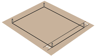
Figure 12.23 – Pegs for each corner
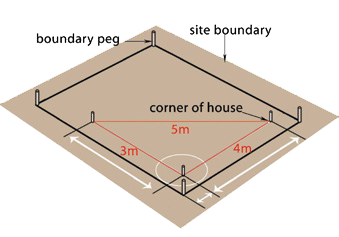
Figure 12.24 – Using the 3,4,5 method to attain a square corner
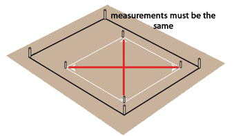
Figure 12.25 – Checking for square
Building Orientation
It is important to try and orientate the layout of buildings and rooms – to maximize the benefits of sunlight. Where possible, have main facades of buildings facing north and south; this makes shading easier and allows maximum use of winter solar gain. Arrange the layout of rooms that are used most and the major areas of glazing placed on the northern side of the building to allow solar heat to penetrate the glazing during the winter months. Living spaces should be arranged so that the rooms where people spend most of their hours are located on the northern side of the building. Uninhabited rooms, such as bathrooms and storerooms, can be used to screen unwanted western sun or to prevent heat loss on the south-facing facades. Where possible the longer axis of the building should be orientated so that it runs as near east/west as possible. Buildings should be orientated in accordance with SANS 204 & SANS 10400:XA, or approximately true north. (This should have already been done in the design phase; however, in many cases this is often ignored)
The following examples are provided from SANS 204 for optimal orientation of buildings in various cities across South Africa:
- Johannesburg – optimal orientation true north ± 15°
- Durban – Optimal orientation true north +5° E and 12° W
- Cape Town – Optimal orientation true north +20° E and 8° W
- Phalaborwa – Optimal orientation true north +15° E and +5° W
- Pretoria – Optimal orientation true north +15° E and +10° W
If buildings cannot be thus orientated, they should be orientated to achieve the lowest possible net energy use.
Figure 12.26 – Orientation Sectors
Foundation excavation/trenching
Carrying on with the example used above – from the measurement of the building, measure out at least one (1) metre and put in more pegs, with a piece of wood nailed horizontally across the top of these two pegs; what is commonly referred to as a profile board. This is to mark the corners of the foundations and other measurements. Measure the width of each foundation trench, for example 600mm, and knock nails into the top of the profile board, to mark the width. Attach a piece of string to each nail and stretch across to the opposite side, marking the foundations. Trenches can be different sizes, depending on loading.
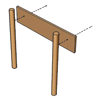
Figure 12.27 – A common profile board
Mark the ground directly under the string with a spade or with dry cement; this will indicate where the trenches need to be excavated.
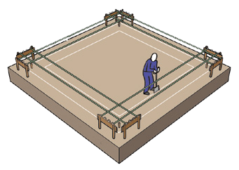
Figure 12.28 – Marking out the foundation using profile boards and lines
Then knock nails into the profile board, this time measuring the width of the wall for example 220mm. The wall must be in the centre of the foundation, i.e. with a 220mm wall, the foundation will be exposed by approximately 190mm for a 600mm width footing on either side of the wall. Excavate trenches to approximately 550mm deep(1), using the lines you have made with a spade or dry cement. Make sure the sides are as plumb as possible, and the bottom as level as possible.
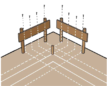
Figure 12.29 – Profile board with nails to mark trench and wall widths
A dumpy level or laser are the most accurate instruments used to ensure that the foundation trench levels or any other related level of the proposed building are level and that levels correspond with what is allowed for in the building plans.
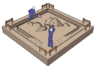
Figure 12.30 – Digging trenches
Shoring
Shoring also called planking, strutting and timbering refers to the temporary supports for sides of excavations and is basically a method of supporting the sides of a trench in order to prevent the sides from caving in or collapsing. Shoring is usually made from planks of wood, set against the sides of the trench, and supported by horizontal planks that span the width of the trench. Shoring should be used where soil is loose and if the trench is over 1.5 metres in depth.
Note: No workers are allowed in trenches deeper than 1.5 metres without the sides being protected or braced.
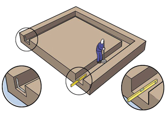
Figure 12.31- Ensure trenches are level and square
There are many reasons why trenches collapse, some of which are listed below:
- Materials too close to the sides
- Excavation plant and equipment too close to the edge
- Unstable subsoil material
- Changes in the moisture content of the soil
Basic shoring terminology
- Poling boards – are typically 1.0 to 1.5 m in length and vary in cross section from 152 x 38 mm to 228 x 50mm. They are placed vertically and support the soil at the sides of the excavation.
- Waling’s – are longitudinal members running the length of the trench and are used to support the poling boards.
- Struts – are square timbers (50 x 50mm or 76 x 76mm or even bigger) that are generally used to support the wailings. They are placed approximately 2.0m centreto- centre to allow for adequate working space between them.
- Sheeting-consists of horizontal boards (usually shutterboard) abutting one another to provide a continuous barrier when excavating in loose soil.
- Runners – are poling boards in continuous formation with tapered base edges. A common size is 228 x 50mm. They are suitable for use in loose or waterlogged soils.
- Puncheons – are vertical supports that are wedged between the waling’s at or near the ends of struts. They are necessary in deep excavations to prevent the wailings from dropping off.
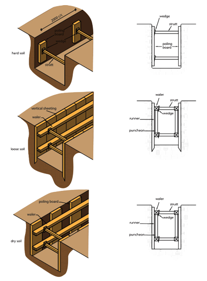
Figure 12.32 – Typical shoring terminology
Stepping
Stepped foundations can be neatly marked out from the original foundation heights, where the ground is sloping. It is good economics to step foundations to save on unnecessary wastage of concrete. It is custom building practice where the foundation is to be stepped to use a brick, in order to stage the brick course height, which will allow for tying in for the foundation brickwork that will follow – see Figure 12.33. When the ground slopes, the trench bottoms must be stepped so that the foundation itself does not slope. The step should be equal to one or more courses of brickwork (i.e. thickness of brick plus one mortal joint).
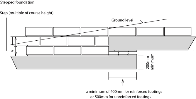
Figure 12.33 – Stepped foundation
Compaction
Excavations should be prodded with a 10 to 12 mm diameter bar prior to the casting of concrete. Uniform penetration should be obtained. Where this is not the case, the soft spots (where penetration is greater than in the surrounding areas), should be dealt with as shown under foundation types – strip foundations.
Placing concrete
Fix pegs in trenches, these should be about 1.2 metres apart, and 200mm high (thickness of footing). This will show you what level to pour the concrete to. Once you have mixed the concrete, pour it into the trench, to the height of the top of the pegs.
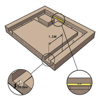
Figure 12.34 – Insertion of pegs for footing heights
Where possible concrete for foundations should be poured in one operation i.e. on the same day; if this is not possible, the concrete should be stopped at steps or other logical linear joints and raked off at an angle to allow adequate joining the following day and not at corners. Start pouring the concrete at the corner furthest away from the mixing site.
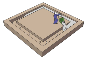
Figure 12.35 – Placing of concrete
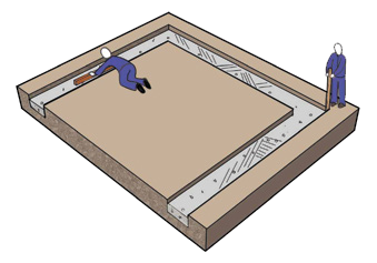
Figure 12.36 – Smoothing of concrete and ramming corners
Level the concrete to the top of the pegs with a straight edge. Ram down the concrete into the corners with a stick to get rid of air bubbles and spaces, i.e. compacting the concrete. It is recommended to leave the foundation concrete to cure for three days before building on it.
Foundation brickwork
Use a straight edge (this is also referred to as a profile) with brick courses marked on it and measure from the peg in the ground, at the highest ground level from the concrete foundation, to about 200mm above the ground level. Mark the peg at the 200mm height above ground level. Then make sure that all corner pegs are level, using a dumpy level.
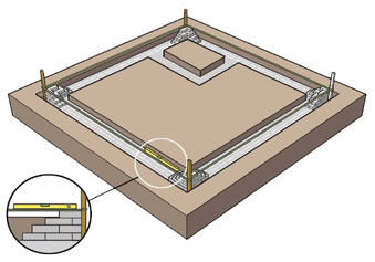
Figure 12.37 Setting out of foundation brickwork
Use a horizontal wooden profile to set out the line and level of the brick walls. Attach string to each nail and stretch it to the opposite piece of wood, in a straight line. This will mark the position of the foundation walls. Mark the position of the wall onto the foundation concrete using a spirit level against the wall line. Mark a point at each end and then shoot a chalk line. When you have drawn the line, use a brick trowel to mark the line into the concrete.
Figure 12.38 – Typical layout of a corner junction
Place bricks without mortar so that they form a corner. The joints separating them should be about 10mm wide. Mark the position of the joints on the concrete foundation, using a brick trowel.
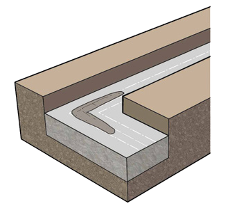
Figure 12.39 – Remove the bricks and lay a bed of mortar for three bricks
Corners in foundation brickwork
Smear the ends of the adjoining bricks and lay them according to the marking of the joints. Build up all the corners first, making sure that each brick course is level and the walls are plumb. The top of all corners should be level with each other. After you have built the corners, build the walls. The foundation walls should be at least 200mm above the highest ground level. Build the walls up to the height of the top of the floor slab.
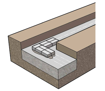
Figure 12.40 – First course layed on mortar
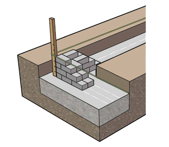
Figure 12.41 – Building up of corner, moving the fish line up each course according to the gauge rod
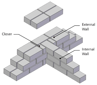
Figure 12.42 – Internal wall T-junction with closers
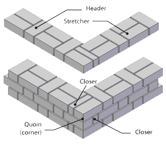
Figure 12.43 – Corner Flemish bond junction with quoin closers
Minimum thickness of foundation walls
The height of any foundation wall not acting as a retaining wall shall not exceed 1.500mm.
The height of any foundation wall not acting as a retaining wall shall not exceed 1.500mm.
- Where a difference in ground level, including backfill, exists between the two foundation walls, such difference shall not exceed 1.000mm.
- No foundation wall shall have a thickness less than the relevant value given in Table 12.8 below; provided that such thickness shall not be less than:
- the thickness of the wall carried by such foundation wall; or
- If it is the wall carried by the foundation wall, the sum of the thicknesses of the leaves of such a cavity wall.
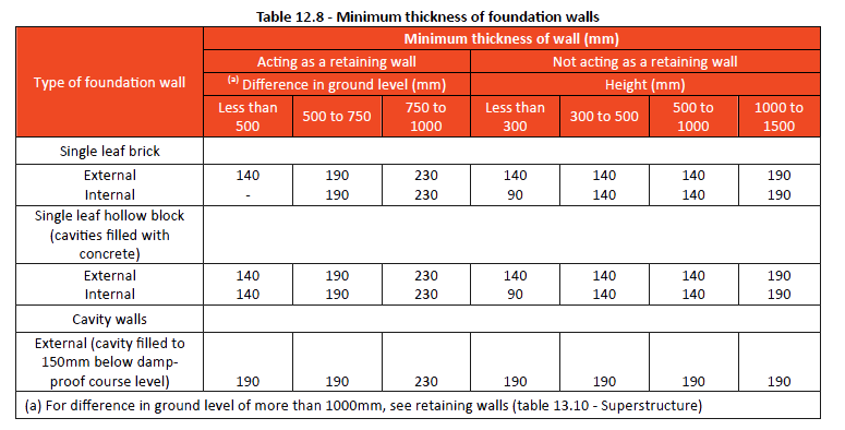
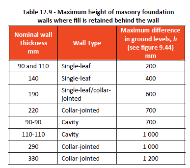
Back filling trenches and under floor slab
Using sand and hardcore fill, (free of grass & vegetation), fill in the trenches on each side of the brickwork and the area beneath the floor slab. The maximum height of fill beneath floor slabs (surface beds) and ‘slab-on-the-ground’ foundations, measured at the lowest point, should not exceed 400 mm unless certified by a competent person, i.e. an engineer. Fill shall be moistened prior to compaction so that a handful squeezed in the hand is firm, but does not show signs of moisture. Fill shall be placed in un-compacted layers not exceeding 100 – 150mm in respect of hand compaction, or 150 – 200mm in respect of compaction by mechanical means.
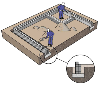
Figure 12.44 – Backfilling trenches and under surface bed
Note: Each un-compacted layer shall be well compacted before additional fill material is added.
Water content and final density of the compacted layers should be carefully controlled, leaving the following typical levels:
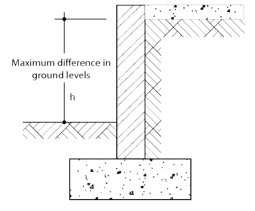
- Outside – levels on the perimeter of the foundation walls after compaction and filling should leave at least 170mm or 2 brick courses below the top level of the foundation walls.
- Internal – Levels of the internal ground below the floor slab, after filling and compaction should leave only one brick course + mortar joint (85mm) above this level. (Generally a minimum of 75mm thick 15MPa concrete is cast on the layer of compacted fill or hardcore).
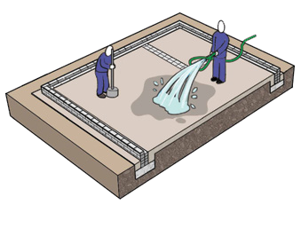
Figure 12.45 – Compaction of the surface bed before placing concrete
Note: A line stretched from the top of the outside brickwork to the opposite side will assist in checking that the level is a constant 75 – 85mm.
Poisoning
Poisoning refers to soil poisoning, of the surface bed and around the foundations. Poisoning is generally for the eradication of termites because they can cause structural damage. Poisoning is a prerequisite required by most financial institutions and local authorities. If there is no
certificate for poisoning, an occupation certificate will not be issued, nor will the final payment be made from a financial institution.
A licensed contractor will generally undertake the poisoning and will issue a certificate once complete. This certificate will need to be produced when handing over a house for occupation.
Note: In some circumstances the soil is poisoned before the backfilling and compaction process starts and again once this process is completed. This depends on the geographical area where the building is situated and whether there is a history of high termite activity in the area. (The contractor doing the poisoning would be able to provide this advice).
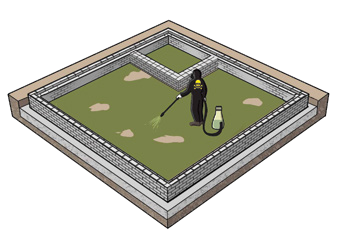
Figure 12.46 – Poisoning of soil beneath the surface bed.
Damp proof membranes
Damp proof membranes used in foundation applications are usually manufactured from impervious materials like embossed polyethylene, available in rolls in different widths and thicknesses known as microns (μm); the most common being 375 μm. It is imperative the product bears the SABS mark in accordance with the National Building regulations.
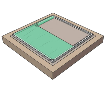
Figure 12.47 – Installing the USB membrane
Under Surface Bed (USB) damp proofing
The purpose of the USB membrane is to prevent water being sucked into the floors and walls of the building by a process of osmosis and as an added precaution against any possible rising damp. The USB membrane is placed over the compacted filling. Make sure the USB membrane reaches the edges of the slab in both directions and covers halfway over the top of the foundation brickwork; usually the inside brick skin. Place bricks on top of the membrane on the brickwork, to keep it in place. Make sure that the USB membrane is tucked well into the corners. If there are any joints that are required in the laying of the USB membrane, make sure the overlap is at least 100mm. The overlapping seam should be taped over using a special tape provided by most manufacturers, or by using duct tape. See figure below.Under Surface bed membranes are usually green – and must be SABS approved and be a minimum of 250 μm (micron).
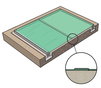
Figure 12.48 – Jointing of USB membrane
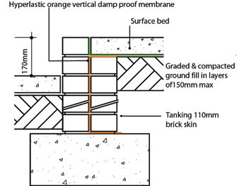
Figure 12.49 – Typical internal step in house – showing vertical damp proof membrane
Note: Vertical damp proofing is very often overlooked and not specified, resulting in numerous buildings having ongoing rising damp problems.
Placing and levelling the concrete floor slab
The whole floor slab should be poured in one day. However, for bigger projects, the slab can be poured in sections, stopping at logical joints, i.e. between rooms. All electrical and plumbing pipes must be taken into consideration and installed before the floor slab is placed; and if required reinforcing. If these pipes and conduits are not installed beforehand, the floor slab may have to be cut, to allow for these services. This will affect the USB membrane and will weaken the floor and lead to cracking.Use a straight board to level and compact the concrete to the top of the foundation walls.
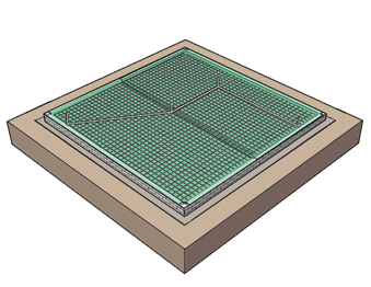
Figure 12.50 – Services must be installed before placing the concrete
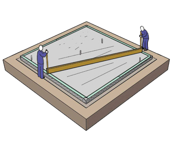
Figure 12.51 – Compacting the concrete floor slab
Construction and movement joints
Construction Joints
Because it is often not possible to place concrete continuously from beginning to the end of construction, a structure is then divided into components of convenient size, known as construction joints to allow for this. Construction joints only really need consideration when. It involves larger type buildings where for example it is impossible to place all the concrete required for the foundations in one day.
Movement joints
There are two main types of movement joints; expansion and contraction:
- Expansion joints are designed to cater for both expansion and contraction of adjacent parts of the structure. They require a sufficiently large gap between the two elements
to accommodate the total amount of expected expansion. - Contraction joints are designed to accommodate contraction, usually related to shrinkage of adjacent concrete only. They may accommodate the contraction of a long concrete strip laid in one operation, or the lateral contraction of a number of concrete strips laid together. Contraction joints are spread more frequently than expansion joints.
Where joints are exposed to the exterior elements, they must be sealed to prevent ingress of water, dust etc.
Installing Thermal Installation
Outline
Thermal insulation has varied applications in the construction of foundations and the superstructure of buildings, which includes; insulating between brickwork, under concrete surface beds, above and below suspended concrete slabs, etc.
Floor slabs
Floor slabs laid on the ground or what we refer to as a slabon- ground (SOG) do not lose heat in the same way as walls and roofs. The ground acts to some extent as an accumulator of heat, and in fact most of the heat loss (approximately 80%) occurs within a short distance of the edges adjacent to the external walls. Consequently, the average heat flow is dependent on the size and shape of the floor. It is possible, if the floor is large enough, to achieve a target U value of 0.35 W/m² °C without the use of any additional thermal insulation, but only in floors usually over 500 m².
For most residential homes, therefore, as for other small buildings, it will be necessary to install insulation around the vertical edge of its perimeter for buildings with a floor area of less than 500 m², with the exception of buildings located within climatic zone 5 (see map on the following page). In terms of the National Building Regulations, the minimum deemed-to-satisfy R-value of the insulation material alone is to be not less than 1,0.
For SOG floor slabs where an in-slab or in-screed heating system is to be added, the entire SOG shall be insulated underneath the slab, regardless of climatic zone. The thickness of insulation will depend upon the thermal conductivity value of the material and the shape factor of the floor. The shape factor is a simple ratio of heated perimeter length divided by heated perimeter area, or P/A. Generally, in South Africa 25mm thick polystyrene board (EPS) will suffice for domestic applications whilst up to 150mm will be required in freezer room applications. In terms of the National Building Regulations, the minimum deemed-to-satisfy R-value of the insulation material alone is to be not than less than 1,0.
Insulating materials, which are susceptible to moisture intake from, for example, condensation, rising damp or rainwater ingress, will offer only reduced values of thermal insulation. It is therefore important to not only consider the initial thermal efficiency requirements but also how this performance is maintained over the long term. It follows that materials, which do not absorb water, are needed where prolonged wetting, for example through dampness rising from below from high water tables, is inevitable.
The insulation value of the floor slab can be further degraded by thermal bridges where high thermal transmission materials penetrate layers of low thermal transmission material, such as may happen at thresholds. Thermal losses due to thermal bridges are often ignored in calculations, especially where thin sections are involved, but these and other components and materials such as concrete floor beams become more important as these energy efficiency standards are adopted.
Some thermal bridges also have serious implications because they produce inside surface temperatures below the dew point of the air, leading to selective condensation on parts of the flooring. Suitable designs can overcome or reduce thermal bridging to acceptable levels. Sealing at joints and around areas where services penetrate the insulation is important.
Where the insulation layer is intended to provide support for a screed or SOG, it will need to have certain minimum structural and other properties such as:
- resistance to loads (using the correct density or grade)
- dimensional stability
- chemical compatibility with the layers above and below (making EPS the ideal choice)
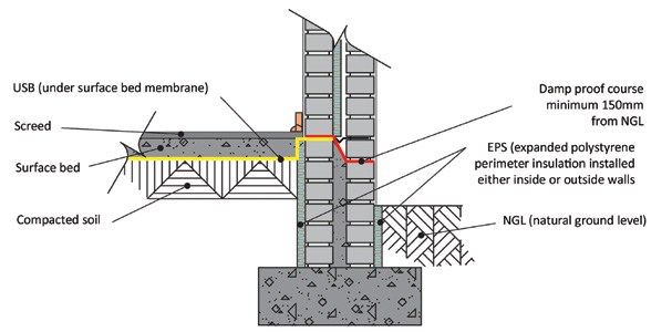
Figure 12.52 – Perimeter or edge insulation
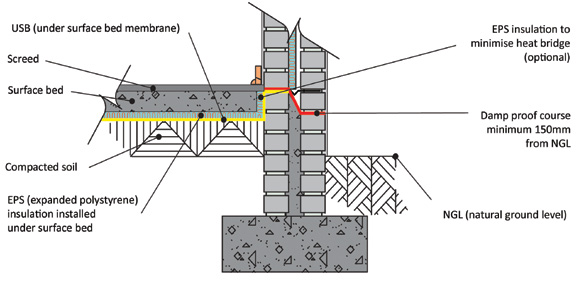
Figure 12.53 – Surface bed insulation (SOG insulation)
Because most thermal insulating materials used in floors have some resistance to moisture vapour, but considerably less than that of a damp proof membrane, it could therefore be necessary with some methods of construction to provide additional moisture barriers to control constructional water. These are often referred to, as vapour control layers or barriers and are typically of polyethylene sheet.
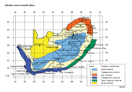

References
Alexander G D & Alexander G C. 2010. Buildaid Building and Pricing Guide 2010/11. Johannesburg: Buildaid Publishing.
Alexander G D & Van As F. 2008: Civil Technology. Johannesburg: EWA Publishing.
Cement & Concrete Institute – www.cnci.org.za
Clay Brick Association – www.claybrick.org.za
Concrete Manufacturers Association – www.cma.org.za
Harrison H W & Trotman P M. 2002. BRE Building Elements – Foundations, Basements & External Works. London: Construction
Research Communications Ltd.
Julyan E L. 1998. Building & Civil Technology. 2nd Edition. Johannesburg.
South African Bureau of Standards – SANS 10400 Part’s A; B; H; K; XA & various other standards. Pretoria. SABS Standards Division.
Van Amsterdam E. 2009. Construction Methods for Civil engineering. Cape Town: Juta & Co.
Van Amsterdam E. 2010. Construction Materials for Civil engineering. Cape Town: Juta & Co.
Cement & Concrete Institute. Fundamentals of Concrete – 2nd Edition. Midrand, South Africa.