Chapter 13
SUPERSTRUCTURE
Cement
Brick Properties and Types
Performance Criteria for Masonry
Window and Door Frames
Other Structural Forms
Concrete Slabs
Brickwork
Fireplaces
Introduction
The superstructure is the actual building you can see and comprises all the elements within a building from the ground slab to the wall plate (roof height) and excludes the roof structure. From a practical point of view greater accuracy is usually required from that of the substructure.
The superstructure can consist of various forms; brick, reinforced concrete, timber and structural steel frames. In this publication we deal mainly with brick structures and only briefly discus the other forms.
This section is the most complex and whilst one shouldn’t get anything wrong on a building project, it is imperative that no mistakes or shortcuts are taken with the theory and methods that follow.
Terminology
Aggregate
Aggregates is the term used for the sand or stone pieces that can be mixed with cement and water to make concrete or mortar.
Arch
An arrangement of bricks over an opening.
Arris
The sharp edges of a brick.
Bat
A portion of an ordinary brick with the cut made across the width of the brick (½ bat, ¾ bat and bevelled bat).
Beam filling
A filling of brick between the roof timber, from wall plate to roof covering, to prevent the entry of birds and vermin and to render the wall weather tight.
Bed
The lower rectangular surface of a brick when placed in position; usually 222 x 106mm.
Brickforce
Light welded material made up of two hard drawn wires (not less than 2.8mm in diameter, not bigger than 3.55mm in diameter), joined at regular intervals either at right angles (ladder) or diagonally (truss type) cross wires. The most commonly used type is the ladder type.
Bed joints
Mortar joints parallel to the beds of the bricks, and therefore usually horizontal in general walling; thickness from 3 to 12mm.
Brick gauge
The height of a brick course.
Broken bond
The use of part bricks to make a good bonding pattern where dimensions do not allow regularised bond patterns of full bricks.
Bull nose
A bullnose is used for copings, or in such positions where rounded corners are preferred to sharp arrises, e.g. window sills.
Butt-joint
A joint between two square-ended pieces of the same thickness without overlap.
Cavity wall
Wall of two leaves effectively tied together with wall ties, with a space between them, usually at least 50mm wide.
Chases
Recesses cut in walls to accommodate service cables or pipes.
Closer
A portion of an ordinary brick with the cut made longitudinally, and usually having one uncut stretcher face.
Compressive strength
The average value of the crushing strengths of a sample of bricks or concrete, tested to assess load bearing capability.
Control Joint
A joint designed to allow sections of a structure or wall to move in a consistent line without weakening the functional reliability of the structure or wall.
Coping
The materials or masonry units used to form a cap or finish on top of wall, pier, or chimney, to protect the masonry below from water penetration. Commonly extended beyond the wall face and incorporating a drip.
Corbel
A feature, or course, or courses of brick projecting from the face of the wall.
Course
One complete level row of bricks in brickwork.
Damp-proof course (DPC)
A course or layer of impervious material which prevents vertical movement of water.
Datum
A fixed reference point from which levels are set out.
Drawing or plans
A construction drawing showing a view of a building or object in a horizontal plane. A floor plan shows the floor area of the building or object in a horizontal plane.
Dumpy Level
A dumpy level is an instrument used in surveying and building to set horizontal heights/levels. The instrument requires to be set level (using a spirit level) in each quadrant, to ensure it is accurate through a full 360° traverse. As an alternative,
laser levels have been developed to provide the same height transfer purpose.
Durability
The ability of materials to withstand the potentially destructive action of natural conditions and chemical reactions.
Efflorescence
The unsightly chalk-like appearance on a building due to the crystallisation of soluble salts contained in the bricks or mortar.
Expanded Polystyrene (EPS)
EPS is used for thermal insulation in foundation walls and floor slabs (SOG [Slab on ground]) as sheets or boards. Loose beads of EPS can also be used as an aggregate for lightweight concrete, plaster or renderings. EPS can also be used for permanent formwork, prefabricated and foundation walls, under floor heating and drainage boards.
Face work
A surface of a brick, such as the header face and stretcher face. The term is also applied to an exposed surface of a wall, which is built neatly and evenly without an applied finish.
Frog
A shallow, sinking formed on either side or both of the 222 x 106mm faces of a brick. A wire-cut brick has no frogs; a pressed brick has two frogs as a rule. A frog provides a good key for the mortar.
Gables
Portion of wall above eaves level that enclosed the end of a pitched roof.
Gauge rod
Batten marked at intervals for vertical setting-out of brick courses.
Gauge boxes
Boxes of specific volumes to accurately measure the proportions of cement, and sand when preparing to mix mortar.
Header
The end surface of a brick; usually 106 x 73mm
Jointing
The finishing off of joints between courses of masonry units before the mortar has hardened.
Lap
The horizontal distance which one bricks projects beyond a vertical joint in the course immediately above or below it.
Lintel
A formed concrete element (which has tensile wires to give it strength, spanning an opening in a wall (e.g. above a door or window frame) to carry the superimposed load.
Lug
A metal fastener that projects out and has a hole in the end for a screw, nail or other fixing for building in. Usually used for building in a window and door frames.
Mortar (dagga)
A specific mix of sand, cement and water, used for bricklaying and plaster.
Movement joint
A continuous horizontal or vertical joint in brickwork filled with compressible material to accommodate movement due to moisture, thermal or structural effects.
Parapet
A low wall around the perimeter of a building at roof level or around balconies.
Pier
A vertical block of brickwork which may either be isolated or attached to the face of a wall.
Perpends (Perps)
Vertical lines controlling the verticality of cross joints appearing in the face wall.
Plumb
The verticality of brickwork.
Prefabricated
A manufactured section of a building or element to enable quick assembly on site, for example, roof trusses.
Quoin
A corner or external angle of a wall.
Raking back
The stepped arrangement formed during the construction of a wall when one portion is built to a greater height than the adjoining wall. No part of a wall during its construction should rise more than 900mm above another wall, if unequal
settlement is to be avoided.
Reinforced brickwork
Brickwork incorporating steel wire (brickforce) or rods to enhance its resistance to loads.
Reinforcing
Reinforcing is used throughout the building process to support and or strengthen the structure. There are various types of reinforcing and each has a specific use – whether
in brickwork or for a concrete slab. It is vital that reinforcing is kept clean of all organic material (such as mud and grass), because this material could cause damage to the mortar. All reinforcing in a building is designed by an engineer.
Retaining wall
A wall that provides lateral support to higher ground at a change of level/
Retempering
To moisten mortar and re-mix, after original mixing, to proper consistency for use (not recommended).
Scaffolding
A temporary framework, usually of tubular steel or aluminium, and timber boards to give access for construction work.
Setting Out
This is the term used for interpreting the floor plan drawing onto the site – placing marks to show where the work is to be located.
Soffit
The exposed lower surface of any overhead component of a building such as a slab lintel, vault or cornice, or an arch.
Stretcher
The side of a brick; usually 222 x 73mm.
Suction rate
The tendency of a brick or block to absorb water from the mortar used for its bedding and jointing. Dense vitrified bricks have a low suction rate; porous bricks have a higher
suction rate – (IRA – Initial Rate of Absorption – affects bonding properties).
Toothing
A full or half brick is removed or a half brick projects from alternative courses of a wall in order to provide adequate bond if the wall is to be joined at a later stage.
Wall tie
Made of stainless or galvanized steel wire and plastic used to connect adjoining walls to each other or to other materials.
Water absorption
The amount of water that a unit absorbs, when immersed in either cold or boiling water for a stated length of time; expressed as a percentage of the weight of the dry unit.
Weep-hole
An opening placed in mortar joints of facing materials at the level of flashing, to permit the escape of moisture.
Standards
As with most industries, the SABS have created standards for the building industry, the applications of which are outlined in the various parts of the National Building Regulations SANS: 10400. This covers provisions or building site operations and building design and construction that are deemed to satisfy the provisions of the National Building Regulations.
The National Building Regulations are statutory requirements that apply to the erection of all building in the country, unless otherwise exempted. SANS 10400 does not specifically outline how to build, but states the minimum requirements regarding everything from the size of rooms to plaster mix. The Rules applying to walls are in Parts K and have been recently revised and cover the following:
- K1 Structural strength and stability
- K2 Water penetration
- K3 Roof fixing
- K4 Behaviour in fire
- K5 Deemed-to-satisfy requirements
The functional regulations K1 to K4 contained in parts K of the national building regulations shall be satisfied where a masonry wall complies with the requirements of SANS 10400:B Structural design; SANS 10400:T Fire protection and fixing of roofs to concrete elements (SANS 10400:K clause 4.4), or SANS 10400:K Clauses 4.2; 4.4; 4.5 and 4.6, which covers the following:
- General
- Masonry walling in single-storey and double storey
buildings - Infill masonry panels in framed buildings
- Free-standing boundary, garden and retaining walls
- Balustrade and parapet walls
- Control joints
- Articulation joints
- Corbeling
- Lintels
- Masonry arches
- Roof fixing
- Rising damp
Extract from SANS 10400 (Part K)
4.2.2 Masonry walling in single-storey and double-storey buildings.
4.2.2.1 Masonry wall panels in single-storey and doublestorey buildings shall have dimensions not greater than those derived from figures 4 and 5 and tables 1 to 6, subject to the maximum lengths of openings and the minimum distances between the faces of supports and openings and between successive openings being in accordance with figure 6 and table 7.
Note 1: The dimensions for panels with openings in tables 1, 2, 4 and 5 are only valid if lintels in accordance with the requirements of 4.2.9 are provided above all windows and openings.
Note 2: Occasionally, during the lifetime of a building, the positions of openings in walls are changed. For this reason, it is recommended that reinforcement be provided in a continuous band in external walls, particularly in the case of walls less than 190 mm thick, to form a lintel or “ring” beam.
4.2.2.2 The distance between an opening and a free edge shall not be less than dimensions “b” given in table 7. Where collar joints in collar-jointed walls are not fully mortared, such walls shall for the purposes of 4.2.1.1 be treated as being cavity walls. Panels incorporating full height doors or doors with fanlights shall be treated as panels supported on one side only and shall be sized in accordance with table 4 (wall with opening).
See – Performance criteria for masonry and Brickwork for more extracts
A full copy of SANS 10400 and its parts should be in every
office of all those involved in the building industry.
Visit the SABS online web store for purchasing standards.
sabs.co.za
Mortars
Table 13.1 – Grading requirements of sands for mortar
| Size of square apertures | Percentage by mass passing sieve | |
|---|---|---|
| (μm-mm) | Fine aggregate for mortar | Fine aggregate for plaster |
| 4,750 | 100 | 100 |
| 2,360 | 90-100 | 90-100 |
| 1,180 | 70-100 | 70-100 |
| 0,600 | 40-100 | 40-90 |
| 0,300 | 5-85 | 5-65 |
| 0,150 | 0-35 | 0-20 |
| 0,075 | 0-12,5 | 0-7,5 |
(Extract from SABS 1090: Aggregates from natural sources – fine aggregate for plaster and mortar)
Outline
Mortar is a mix of cement (lime is sometimes added), water and sand (fine aggregate). Mortar binds bricks and blocks together to give strength and stability to a wall. Freshly mixed mortar must be soft and plastic so that it spreads easily and makes good contact without becoming too strong. Too strong a mortar may crack and is wasteful as it is more expensive.
Sufficient mortar should be mixed only to provide immediate use. Once mixed, no further water should be added to change the workability of the mix.
Workability
Workability is a property which describes how easily mortar can be spread over the masonry unit and affects the performance and the productivity of the artisan. In almost all cases there is a specific mortar, which will best suit the project and the required workability; for example, the type of masonry unit, degree of exposure, local aggregate, and season, will all affect the workability.
Lime
The use of lime in mortar mixes is optional. Lime imparts the properties of plasticity and water retention to mortar. The latter property is important as it prevents mortar drying out, resulting in the incomplete hydration of the common cement.
Lime used in mortar is hydrated lime (commercial bedding lime) complying with SABS 523:1999; and not quicklime or agricultural lime. Lime gives the best results when used with coarse sands. Lime with clayey sands can make the mortar over-cohesive and difficult to use.
Lime should be used if the sand lacks fine material or is single sized, as such sands tend to produce mortar with poor workability unless lime is included in the mix.
Lime also helps the fresh mortar to retain water when it is spread against dry cement bricks or blocks and helps to prevent cracking of the hardened mortar. A maximum of 40ℓ of lime is permitted per 50 kg of cement.
Note: Do not use lime with masonry cement.
Mortar plasticisers
Mortar plasticisers exercise a desirable effect on the workability and plasticity of the mortar in which they are used. Generally, the admixtures have no effect on setting time (they do not accelerate or retard the mortar setting) but may cause air entrainment.
The use of mortar plasticisers is optional. Their effectiveness varies with the quality of sand, the composition of the cement, its fineness, the water-cement ratio, temperature of the mortar, volume of plasticiser and other factors or site conditions.
Aggregates
The sand should be clean (grass, leaves, roots, etc., are harmful) and it should not contain too much clay. Sand for mortar should comply with SABS 1090 and consist of hard particles which range in size from dust up to about 4.750mm, in accordance with Table 13.1.
In the assessment of mortar sands, grading is only one factor to be considered, with shape, surface area, character of fines and average particle size of the sand also being important.
Pit sands generally have these characteristics. River, dune and beach sands are often too uniform in size (single sized) to give good results.
A simple practical field test that includes these factors is the Cement and Concrete Institute test.
Provided that a sand yields a smooth, plastic and cohesive mix, its quality, based on “water demand” can be determined by the following test.
The quantities used should be weighed on a kitchen scale that is accurate, and the test should be carried out on a smooth impervious surface. It is also important that the sample used is fairly representative of the bulk supply.
Procedure:
- Dry out a wheelbarrow full of sand to be tested.
- Weigh 5 kg cement and 25 kg of dry sand. Measure 5 litres, 1 litre and 1,5 litres of water into separate containers.
- Mix the cement and sand until the colour is uniform. In succession, mix in each of the volumes of water (5 litres, 1 litre and 1,5 litres) until the mix reaches a consistency suitable for spreading or plastering.
Then:
- If 5 litres is enough – the sand is of “good” quality
- If 5 litres + 1 litre is enough – the sand is of “average” quality
- If 5 litres + 1 litre + 1,5 litres is enough – the sand is “poor”
- If more than 7,5 litres is needed – the sand is “very poor”.
A “good” or “average” sand should be used for mortar in walling below the damp-proof course.
Note: Concrete bricks and blocks should not be wetted before being laid. Burnt clay bricks should be wetted before being laid.
Mortar for blockwork
The cement in the mortar mix is usually adjusted when using blocks to suit the weight and absorption rate of the block used. Whenever cement blocks are dry and dusty, especially during dry weather conditions, high suction of water results. If so, the mortar should be fattened by reducing the sand content or by the addition of a plasticiser, or lime.
In some instances the pit sand can be blended with a coarse sand (for example, river sand with a particle size of less than 3,0 mm) to make the mortar more workable when using heavy blocks.
Ready-mixed mortar
Ready-mixed mortar with an extended board life has been successfully used over a number of years. Ready-mixed mortar has advantages of convenience on site as it is delivered at a consistency ready for use. Usually it is delivered in readymix trucks or containers. It is stored in containers on site in a protective manner that minimises loss due to evaporation and protects the mortar from freezing in cold weather. No other materials or admixtures are added on the site.
The mortar contains a regulator, which is a retarding type admixture, which controls the initial hydration period of the cement. This allows the mortar to remain plastic and workable for a period, generally between 24 and 36 hours, but sometimes as long as 72 hours. At any time during this period when the mortar is used, suction by the masonry units will occur and initial set takes place in a normal manner.
The early strength that develops is satisfactory for the walls to be constructed at a normal rate and the mortar will retain enough water to ensure long-term strength development.
Ready-mixed mortar
Table 13.2 – Mortar strength requirements and mix proportions
| Mortar class | Minimum required at 28 days (MPa) | Quantity of sand per 50kg bag of cement (ℓ) | Quantities of materials required per m³ of mortar (not including wastage) | |||||
|---|---|---|---|---|---|---|---|---|
| Preliminary laboratory tests | Works tests | Common cement 32,5 – 42,5 |
Masonry cement 22,5X |
Common cement bags 32,5 – 42,5 |
Sand m³ | Masonry cement bags 22,5X |
Sand m³ | |
| I | 14.5 | 10 | 130ℓ | 80ℓ | 10 | 1.25 | 13.5 | 1.15 |
| II | 7 | 5 | 200ℓ | 130ℓ | 7 | 1.35 | 10 | 1.25 |
The proportion of each material in the mix should suit the type of work being done. Strength requirements and mix proportions, recommended by the Cement and Concrete Institute, are given in Table 13.2 on the following page.
Mortar must not be used after it has started to set, which usually occurs about two hours after it has been mixed. One man – particularly if he is a weekend builder – can probably lay a little more than 60 bricks an hour. If you are working on your own or with one assistant, it is better to mix a number of small batches as they are required than to mix a one-bag batch. Do not use too thick a layer of mortar between bricks or blocks; this is wasteful and may lead to cracking.
Mortar class
In general terms the classes of mortar may be used as follows:
Class I:
Highly stressed masonry incorporating high-strength structural units such as might be used in multi-storey loadbearing buildings; reinforced masonry.
Class II:
Normal loadbearing applications, as well as parapets, balustrades, retaining structures, and freestanding and garden walls, and other walls exposed to possible severe dampness.
In practice, Class II mortars are used for most applications. Although SABS 0249:1993 refers to a Class III mortar, it is so seldom used that it has been omitted from Table 13.2. Other proportions may be used if these can be shown by test to be satisfactory.
Bond between mortar and masonry
Strength between mortar and masonry units is a more representative property of both the tensile and flexural strength of walls. Bond strength is important in relation to the permeability of masonry. Rain water usually penetrates a wall through fine cracks between the masonry units and the mortar, and only rarely through either the masonry units or the mortar.
The greater the strength of the bond between mortar and masonry, the greater is the resistance to leakage. Bond depends largely on the balance between initial rate of absorption (IRA) or suction of the unit and the water retention properties of the mortar.
Mortars shrink on drying and the magnitude of drying shrinkage is directly related to the water requirement of the mortar sand.
Pigments
Pigments may be used to colour mortar, with the dosage depending on the specific colour required. The recommended limit on mineral oxide content is 7% of common cement content. Pigmented mortar with face brickwork can change the appearance of a building dramatically.
Batching the materials
A builder’s wheelbarrow is a convenient measure for large batches; the capacity is ± 65 ℓ. Steel drums of 20 ℓ or 25 ℓ capacity and buckets are useful for small batches. Check the capacity of drums and buckets when filled to the brim as this is often more than the nominal capacity. To batch, shovel material into the measure and then strike off level with the brim.
Mixing
Mixing should be done on a clean hard surface such as a smooth concrete floor or a steel sheet. Small batches may be mixed in a wheelbarrow provided that the volume of the batch is no more than half the capacity of the barrow.
Sand and cement, and lime if used, should be mixed until the colour of the mix is uniform. Then add water in small quantities, mixing after each addition, until the mix is soft and plastic.
Handling on site
If mortar is left in the sun before being used, it should be covered with plastic sheeting or a wet sack. Discard mortar that has stiffened so much that it is impossible to restore workability without adding more water.
Cement
Table 13.3 – Compressive strength requirements
| Strength class | Compressive strength (MPa) | |||
|---|---|---|---|---|
| Early strength | Standard strength | |||
| 2 days | 7 days | 28 days | ||
| 32,5N | – | ≥ 16,0 | ≥ 32,5 | ≤ 52,5 |
| 42,5N | ≥ 10,0 | – | ≥ 42,5 | ≤ 62,5 |
Standard mortar prisms with w/c ratio = 0.50
See Foundations – Cement, for more information on other properties of common cement.
Outline
In South Africa, Cements for use in mortar shall be common cements complying with SANS 50197-1, and masonry cements complying with SANS 50413-1; strength class 22,5X. A site blend of a common cement and a cement extender can also be used on larger type projects where the mortar is specifically designed for the project.
The performance of masonry cements claiming conformance with SANS 50413-1: strength class 12,5X are not supported by independently published data. The guidelines to the correct cement choice relate to three basic criteria:
- Strength requirement
- Environmental considerations/durability
- Requirements dictated by applications and construction methods
In many instances, a single criterion may be enough for the specifier to choose a cement especially for mortar, while in other instances all three may be required, for example when choosing a cement for concrete
Types
Common cements
Common cements are manufactured in five categories according to composition, designated CEM I to CEM V. CEM I consists essentially of Portland cement on its own. CEM II to CEM V are factory blends of Portland cement and a cement extender, or a filler such as finely ground limestone.
The following common cement designations and strength classes are suitable for mortar.
Table 13.3 – Compressive strength requirements
| Cement designation | Strength class |
|---|---|
| CEM I | 42,5 |
| CEM II A-L | 32,5 |
| CEM II A-M | 32,5 |
| CEM II A-S | 32,5 |
| CEM II A-V | 32,5 |
| CEM II B-L | 32,5 |
| CEM II B-S | 32,5 |
| CEM II B-V | 32,5 |
| CEM II B-M (L-S) | 32,5 |
| CEM III A | 32,5 |
Refer – SANS 50197-1: (Table 2) for full details on the composition of each of the above products.
It is clear from the above that more than one cement can provide the required strength and that strength class 32,5N can be used in most mortar applications if the mix design is appropriate. The strength class of common cements is measured in a standard test at ages 2 or 7 days, and at 28 days. The strength class designated to each type is the minimum 28 day strength requirement in terms of SANS 50197 -1. (‘N’ after the strength class denotes a class with normal strength development and an ‘R’ denotes a class that achieves better early (rapid) strength)
Masonry cements
These are cements formulated primarily to impart good workability to mixes for plastering and masonry. Masonry cements are a blend of Portland cement and finely ground limestone or hydrated lime. Some masonry cements include an air-entraining agent. Do not use lime with masonry cement.
! Note: Masonry cements that comply with SANS 50413-1 are not intended for use in concrete.
Storing and handling
Cement is sold in 50 kg bags and in bulk. Cement must be kept in dry storage. If there are hard lumps in the cement that cannot be crumbled by hand, it is not fresh and should not be used.
Brick properties and types
Outline
Bricks and blocks (masonry units) are the most basic building components utilized in the construction of any structure. Bricks have changed in shape and size over centuries. There are many different types available; not only in size but also colour, texture and strength. Masonry units are classified both by their quality, which affects their use, and the manufacturing process and can be divided into two distinct categories, being; Clay and Concrete (concrete bricks or blocks are sometimes incorrectly referred to as cement bricks or blocks). Clay Bricks are manufactured from a mixture of Clay and other additives, which are mixed together to make a pliable type mixture almost like plasticine, which is then shaped usually by extrusion and cut to size, then dried and fired.
Different clays produce the different colours – in most cases the clay contains some traces of iron oxide that will give most clay bricks a reddish colour. Concrete bricks and blocks are manufactured from various types of aggregate (sand and other materials like ash mixed with small stone particles) creating the texture and colour, mixed with cement and water, which is then vibrated into a mould creating the shape and size and profile of the brick or block. The moulded products are then cured either in steam chambers or in the air and are regular in size and colour.
Modular co-ordination
Modular co-ordination is a method of co-ordinating the dimensions of buildings and building components to reduce the range of sizes required and to enable components to be built in on site without modification. For modular co-ordination, the dimensions of components and the space to be filled by them must be related to a single denominator, the basic module. The South African Bureau of Standards has accepted 100 mm as the basic module for horizontal and vertical dimensions. Buildings should be dimensioned to incorporate controlling dimensions which provide for the necessary co-ordination of dimensions to accommodate all modular size components, assemblies and units.
Setting out is simplified because most dimensions will be multiples of 100mm, though with concrete block masonry a 200mm module is preferable. Furthermore brick and block sizes need to have dimensions that provide the ideal width for the human hand to lift and place with the minimum of strain as well as allowing the bricks and blocks to be bonded in any direction.
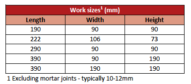
The most commonly used and manufactured brick size is the “Imperial Brick”; with the following nominal dimensions – 222 mm long x 106 mm wide x 73 mm high- see figure 13.1. The use of modular size masonry units is essential if buildings are designed to the 100mm standard module – as stated in SANS 993 modular co-ordination in building. Modular planning is based on a nominal joint thickness of 10-12mm. Modular wall thicknesses are 90,106,140 and 190mm. Several sizes of bricks and blocks are made by individual manufacturers.
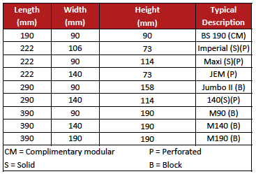
Various combinations of these dimensions are illustrated in the table on the following page. Non-modular sizes of units are found in practice not to bond well without considerable cutting of the units. English or Flemish bond and construction of square brick piers is not possible as such units deviate from the basic principle of masonry bonding where the length of a unit should be twice its width plus the thickness of the bedding or perpendicular joint. Generally, for easier, cost effective and sound building practice, the unit size should be based on the principles of modular co-ordination as per the table.
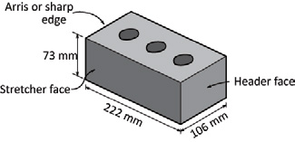
Figure 13.1 – Dimensions of a brick
Bricks
Most bricks are usually manufactured to the imperial size 222 mm (i.e. 2 modules) horizontal and 106mm (1 module) vertical. There is a rough arithmetical relationship of length to width of 2:1 and length to height of 3:1 in the standard or imperial brick of 222mm long x 106mm wide x 73mm high and when used with a recommend 12mm mortar joint, the following formats can be used:
- The format size becomes 234 x 118 x 85mm.
- The format length (234) is the spacing of stretche perpends.
- The format width (118) is the spacing of header perpends
- The format height (85) is the coursing height.
Blocks
The most popular co-ordinating block dimension is 400 mm (i.e. 4 modules) horizontal and 200 mm (2 modules) vertical. To make up the design lengths and heights it may be necessary to use, other than the basic size block, blocks having co-ordinating lengths of 100, 200 and 300mm and a co-ordinating height of 100mm. These sizes may be achieved by using specific blocks of suitable modular dimensions. If a unit is of modular dimensions, and is so described, it will fit into a modular space on the design grid.
Vertically, a co-ordinating height of 100mm may be achieved by the use of bricks or blocks of 90mm nominal height. A modular dimensioned solid block manufactured with low-density aggregates such as clinker used in 140mm thick external walls is 290mm long x 140mm wide x 90mm high and when used on its side in 90 mm thick internal walls is 290mm long x 90mm wide x 140mm thick.
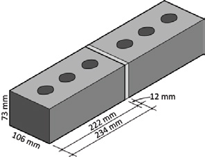
Figure 13.2 – Dimensions of a brick plus mortar joint
Properties
Size
Size varies depending on category, type and the manufacturing process. When describing the dimensions of a masonry unit, the standard procedure is length x width x height (all in millimetres).
Water absorption
Water absorption is the percentage increase in the weight of a dry masonry unit when it has been saturated. It is one of the parameters for definition of engineering bricks and damp-proof-course bricks. It affects rain penetration through the outer skin of a wall (typically in a cavity wall) and is used to define the flexural strength in lateral load design. The water absorption test requires a masonry unit to be soaked in a bath of water for 24 hours to determine its ability to absorb water. Depending on the type of masonry unit, this will range from 5% to 15%. The more porous the unit, the more water it can absorb.
Water absorption of masonry units is not specified in SANS 1215. It is not regarded as a significant characteristic where weather conditions in South Africa are mild and where freezing and thawing seldom occur. Water absorption is a measure of water absorbed in a masonry unit and does not necessarily measure or describe the porosity or permeability of a unit.
A further consideration is the Initial rate of absorption (IRA) which is specified in SANS 10164 Part 1: and is a measure of the amount of water absorbed into the bed face of a masonry unit in one minute, i.e. initial suction. Masonry units with a more sensitive IRA can affect bonding of mortar to the masonry unit. Masonry units with an initial rate of absorption exceeding 1,8kg/m² min. should be moistened prior to laying to reduce the rate to between 0,7 and 1,8kg/m² min.
Compressive strength
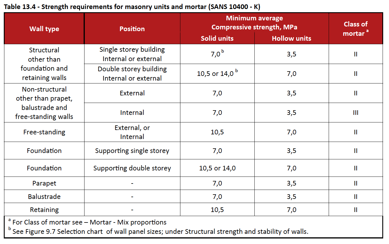
A wide range of masonry units is available in this country and they vary in compressive strength for a number of reasons, like the differing qualities of raw material and the manufacturing method. The compressive strengths can range from 3,5MPa to greater than 50MPa. The compressive strength of a unit is the mean of 12 crushing tests in which the failing load is divided by the gross area of the masonry unit. The class of masonry unit required is referred to as nominal compressive strength in SANS 1215 and in SANS 10400-K and SANS 2001-CM1 as average compressive strength.
Soluble salt content
Most clays when used in the manufacturing process contain soluble salts that may be retained in the fired bricks. If brickwork becomes saturated for long periods, soluble sulphate may be released. This sulphate attack may cause mortars that have been incorrectly specified or batched and have a low cement content to deteriorate.
Efflorescence
Efflorescence is harmless and usually temporary. It can be minimized by protecting masonry units from rain at the early stage of construction and normally takes one of three forms: lime bloom; lime weeping; and crystallisation of soluble salts.
Lime bloom
The most common form of efflorescence is lime bloom and it is particularly noticeable on coloured masonry units. It is a white deposit which is apparent either as white patches or as an overall lightening in colour. The latter effect is sometimes mistakenly interpreted as the colour fading or being washed out. The cause of lime bloom lies in the chemical composition of cement. When water is added to cement, a series of chemical reactions take place which result in setting and hardening. One product of these reactions is “lime” in the form of calcium hydroxide. Calcium hydroxide is slightly soluble in water and, under certain conditions, can migrate through damp concrete or mortar to the surface and there react with carbon dioxide from the atmosphere to produce a surface deposit of calcium carbonate crystals.
This surface deposit is similar to a very thin coat of whitewash and gives rise to the white patches or lightening of colour mentioned previously. The surface deposit is normally extremely thin and this thinness is demonstrated by the fact that, when the masonry unit or mortar is wetted, the film of water on the surface usually makes the deposit transparent and the efflorescence seemingly disappears. The occurrence of lime bloom tends to be spasmodic and unpredictable. Nonetheless, an important factor is the weather. Lime bloom forms most readily when masonry units or mortar becomes wet and remains damp for several days, and this is reflected in the fact that is occurs most frequently during the winter months. Extended periods of rain and cold weather in particular are conditions most likely to precipitate a severe manifestation.
Although drying winds are often suggested as a likely cause, they are probably not a major factor. Lime bloom is not visible on damp surfaces and so only becomes apparent with the onset of dry weather. Thus, dry weather does not necessarily produce lime bloom; it may only make visible a deposit which had already formed but could not be seen because the masonry unit or mortar was damp. Lime bloom is a temporary effect and, given time, usually disappears of its own accord. It is purely superficial and does not affect the durability or strength of the masonry units.
Lime weeping
Lime weeping is an encrustation or build-up of white material on the surface of a masonry unit. It usually occurs at joints or cracks, or at DPC level where water emerges from the interior of a wall onto the surface. Lime weeping is closely related to lime bloom. Water moving across or through concrete, deposits this lime as calcium carbonate. However, unlike lime bloom, the calcium carbonate is not deposited as a thin surface layer, but builds up to form thick encrustation in localised areas. Lime weeping is a process very similar to that which produces stalactites and stalagmites in caves in limestone rocks.
The presence of lime weeping does not normally give rise to concern about the durability of a structure. It is, however, an indication that water is flowing through the masonry and this may be undesirable.
Crystallisation of soluble salts
This type of efflorescence is a crystalline (whitish) deposit normally observed on the surface of clay masonry after the evaporation of water carrying dissolved soluble salts; it is relatively rare on concrete masonry. It usually takes the form of a fluffy deposit.
Thermal movement
Bricks expand on being warmed and shrink when cooled. It is the expansion and contraction of the brickwork as a whole and not a single unit that requires consideration when designing a building.
An increase in the temperature of a wall will induce expansion. The degree of movement is equal to the temperature range multiplied by the appropriate coefficient of thermal movements overcoming restraint in the wall itself – see Table (x) below.
A decrease in temperature will result in the shortening of the wall that may induce cracks. However, the movement that actually occurs within a wall after construction depends not only on the range of temperatures, but also on the initial temperatures of the units as laid, their moisture content and the degree of restraint.
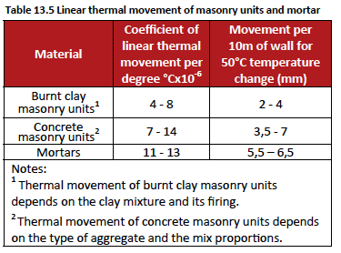
To determine the effective free movement that could occur, therefore, some estimation of the initial temperature and temperature range has to be made. The effective free movement that is calculated should still be modified to allow for the effects of restraints.
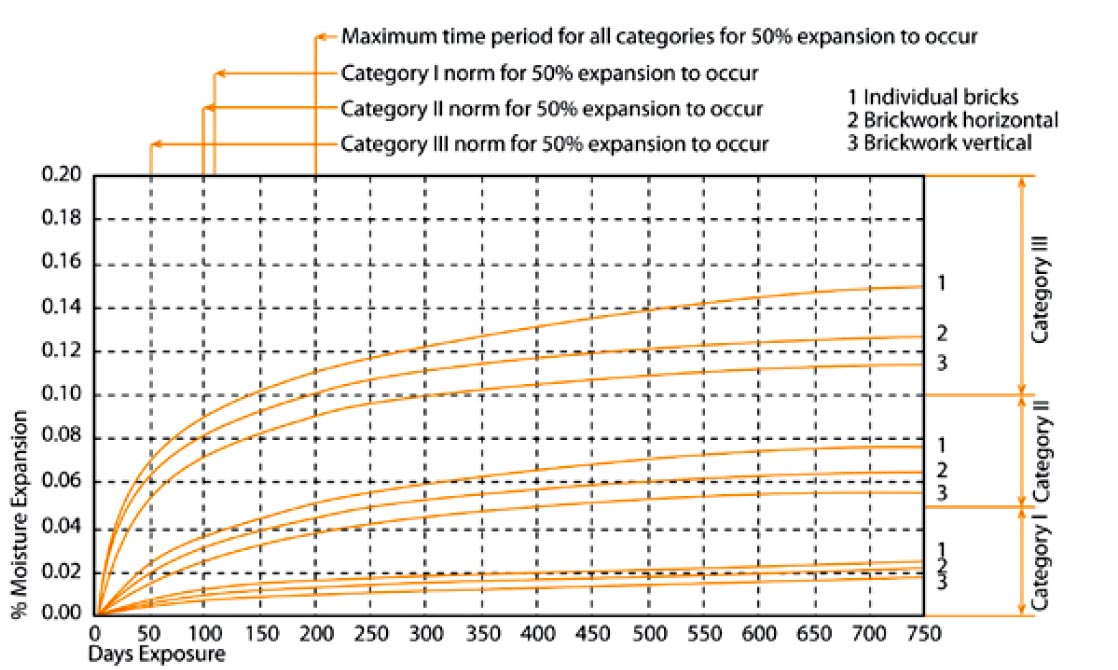
Irreversible moisture expansion/movement
Clay masonry units expand on cooling from the kiln as some of the water molecules reattach themselves after being driven off by the heat of the kiln. This expansion is irreversible/nonreversible unless the bricks are re-fired. This continuing expansion of clay masonry units can be avoided by using mortar that can accommodate at least some of the expansion, avoiding designs such as short offsets in long runs of brickwork, and by incorporating adequate movement joints.
SABS 0249 recommends design for potential movement due to moisture expansion, in mm/m, of:
- < 0,5 for category I bricks
- 0,5-1,0 for category II bricks, and
- 1,0-2,0 for category III bricks.
Burnt clay masonry units undergo an irreversible moisture expansion, which occurs as a result of the absorption of moisture from the atmosphere after firing. This expansion, which is characteristic of all porous ceramic products, commences once the unit starts absorbing moisture from the atmosphere – hence the term moisture expansion.Moisture expansion must be considered and designed for when using clay masonry units in a building – see Figure 13.3 below. Burnt clay masonry units, in general, shall have an irreversible moisture expansion of not more than 0,20% and, in faced applications, a demonstrated satisfactory performance with respect to durability, unless it can be reasonably demonstrated by other means that the units are fit for purpose.
Notes on irreversible moisture expansion:
- There is no difference in the expansion of perforated and solid bricks. Bricks stored in air expand in the same manner as bricks cooled from the kiln in a drier
- There are no cost-effective ways of accelerating the irreversible moisture expansion of ceramic materials.
- The rate of expansion decreases steadily with the passage of time.
Durability
The best indicator of a product’s durability performance in any application is at least five years’ satisfactory performance in the application concerned. A single value of compressive strength alone is not an adequate criterion for a product’s likely durability in an exposed application. For example, the present minimum requirement for facing of 17MPa average compressive strength fails to cater for the requirements of more severe exposure.
Currently, a direct determination of durability does not exist in the form of a proven accelerated weathering test or some other performance-based evaluation, although a programme of research and of measuring the performance of products is ongoing. Durability is the ability of a material to withstand the combined effects of the weathering agents of moisture, soluble salts, frost and thermal changes. Exposure is the severity of these weathering actions, varying from mild to severe, and depending on both regional geographic conditions, and micro-climatic conditions with regard to the building’s height and the material’s position within the building. Parapets and copings, for example, are clearly subject to more severe exposure conditions than face brickwork protected by overhanging eaves. Internal face brickwork is not subject to the same degree of exposure as external, unrendered brickwork.
The use of facings and non-facings selected for durability in an area geographically close to the factory manufacturing the masonry units poses few problems. The local knowledge of the exposure conditions and of the performance of the masonry units concerned, which is generally available from the brick manufacturer, specifiers and building contractors, will ensure that only products suited for the intended purpose, will be used. It is when masonry units are specified by an architect or client far from the location of the manufacturer, with the building under taken by a contractor who is not familiar with the properties and performance of the particular masonry unit, that the risk of a masonry unit being used that is not suited to a particular application is increased.
Besides the use of masonry units of satisfactory quality and durability, attention should be given to the type and quality of the cement and sand used in the mortar mixes; the avoidance of admixtures that may cause corrosion of reinforcement; the cover to reinforcement and wall ties; and the positioning and sealing of control joints where used.
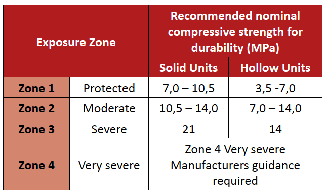
Masonry units are normally sufficiently durable to resist local exposure conditions for the intended life of most buildings and the durability of masonry units is generally related to compressive strength. Recommended nominal compressive strengths can be taken as a guide where there is no surface protection of the masonry units, as illustrated in the table below. Exposure zones In parts of Southern Africa, where the climate and peculiar local conditions combine to produce a harsh environment, certain types of masonry units used externally may suffer from weathering; especially when using face bricks. Broadly, experience and SABS 0249: Masonry Walling has shown that Southern Africa may be grouped into four exposure zones.
Zone 1 Protected:
All inland areas more than 30 km from the coastline
Zone 2 Moderate:
The 30 km zone along the coast, but excluding the sea spray zone
Zone 3 Severe:
This consists of the following:
- the sea spray zone such as the seaward sides of Durban Bluff and other exposed coastal headland areas;
- the 15 km coastal zone from Mtunzini northwards to the Mozambique border, including Richards Bay; and
- the coastal belt of Namibia
Zone 4 Very severe:
- areas such as Walvis Bay where moisture from the sea mist and high ground water tables, soluble sulphates in the soil, and/or rapid temperature changes combine to create the most severe exposure and weathering conditions; and
- industrial areas where high acid or alkaline discharges occur
Types
Common or stock bricks In South Africa we use the term stock brick instead of calling them common bricks. The quality of these bricks varies considerably because they are normally cheaper and are suitable for general-purpose use with no special appearance of a facing.
Masonry units – Clay
NFP – Non-Facing Plastered
Clay bricks suitable for general building work and when used externally require being plastered.
NFX – Non-Facing Extra
Clay bricks suitable for use, plastered or un-plastered; for general building work below damp-proof course or under damp conditions or below ground level where durability rather than aesthetics is the criterion for selection; sometimes referred to as footing or foundation bricks.
Masonry units – Concrete
Concrete common bricks can be used externally without further protection (i.e. plastering) and can be adequately durable and frost resistant.
Face bricks
Face bricks are produced to withstand most environmental conditions as well as provide an aesthetic appearance and do not require and further protection.
Facing and engineering bricks are sometimes pressed after being wire cut to provide smoother faces and sharper arises. Holes formed during the extrusion process vary considerably in number and size. Bricks with a total volume of holes less than 25% of volume of the brick are called perforated bricks.
The advantages of perforated bricks include a reduction in process times, reduction in weight and therefore easier handling on site and some increase in thermal value. The perforations do not appear to affect rain penetration through walls. As the holes go right through the bricks when laid vertically, they are vulnerable to saturation from rain during construction. Saturation may increase drying-out time and increase the probability of what is termed construction water or dampness and may therefore inhibit early decoration, such as painting, due to wet walls.
Clay face bricks are sub-divided into three categories:
FBS – Face Brick Standard Clay
bricks that are selected or produced for their durability and uniformity of size and shape
FBX – Face Brick Extra Clay
bricks that are selected or produced for their durability and high degree of uniformity of size, shape and colour
FBA – Face Brick Aesthetic Clay
bricks that are selected or produced for their durability and aesthetic effect deriving from non-uniformity of size, shape or colour Non-Facing Extra bricks are commonly used as a fair face brick externally with a cement wash plaster or can be used as a semi face brick.
Engineering units
Any class masonry unit produced for structural or loadbearing purposes in face or non-face work,
where the manufacturer supplies clay bricks to an agreed compressive strength. An engineering unit is
designated by the addition of the letter E followed by a number equal to the nominal compressive strength in megapascals, e.g. FBSE21.
Special bricks
A range of special shapes are available from certain manufacturers to enhance to aesthetic detailing of buildings. The common specials available are the cants and the bullnose bricks.
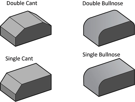
Figure 13.4 – Special bricks
Blocks
The difference between a brick and a block is a matter of size, not material and blocks are usually hollow. Concrete blocks are used for both internal and external walls. It is often recommend that they are plastered to provide extra protection against moisture. Blocks are generally used in low-cost housing because they are less expensive than normal stock bricks and speed up construction.
The use of concrete and clay masonry units in the same wall
Concrete and burnt clay masonry units respond differently to temperature, moisture and stress. Consequently when used in the same wall distress may occur. It is therefore not recommended that dissimilar materials be used in the same leaf.
Masonry units – Clay
After manufacture, some clay bricks expand slowly in contact with water or humid air; this expansion is not reversible by drying at atmospheric temperatures; the movement is termed moisture expansion and continues for a number of years. In an unrestrained wall, a temperature change of 20ºC results in movements of approximately 0,1mm per m horizontally and 0,2mm per m vertically.
Creep – deformation in time under stress – is generally less for clay than for concrete units but, except in highly stressed load-bearing structures, this is not a significant factor in design.
Masonry units – Concrete
For a short period after manufacture, concrete masonry units shrink due to loss of moisture and carbonation. Initial drying shrinkage should be substantially complete before units are built into the wall. Concrete masonry units expand with a gain in moisture and contract with loss of moisture. In an unrestrained wall, a temperature change of 20ºC results in horizontal and vertical movements of
approximately 0,2mm per m.
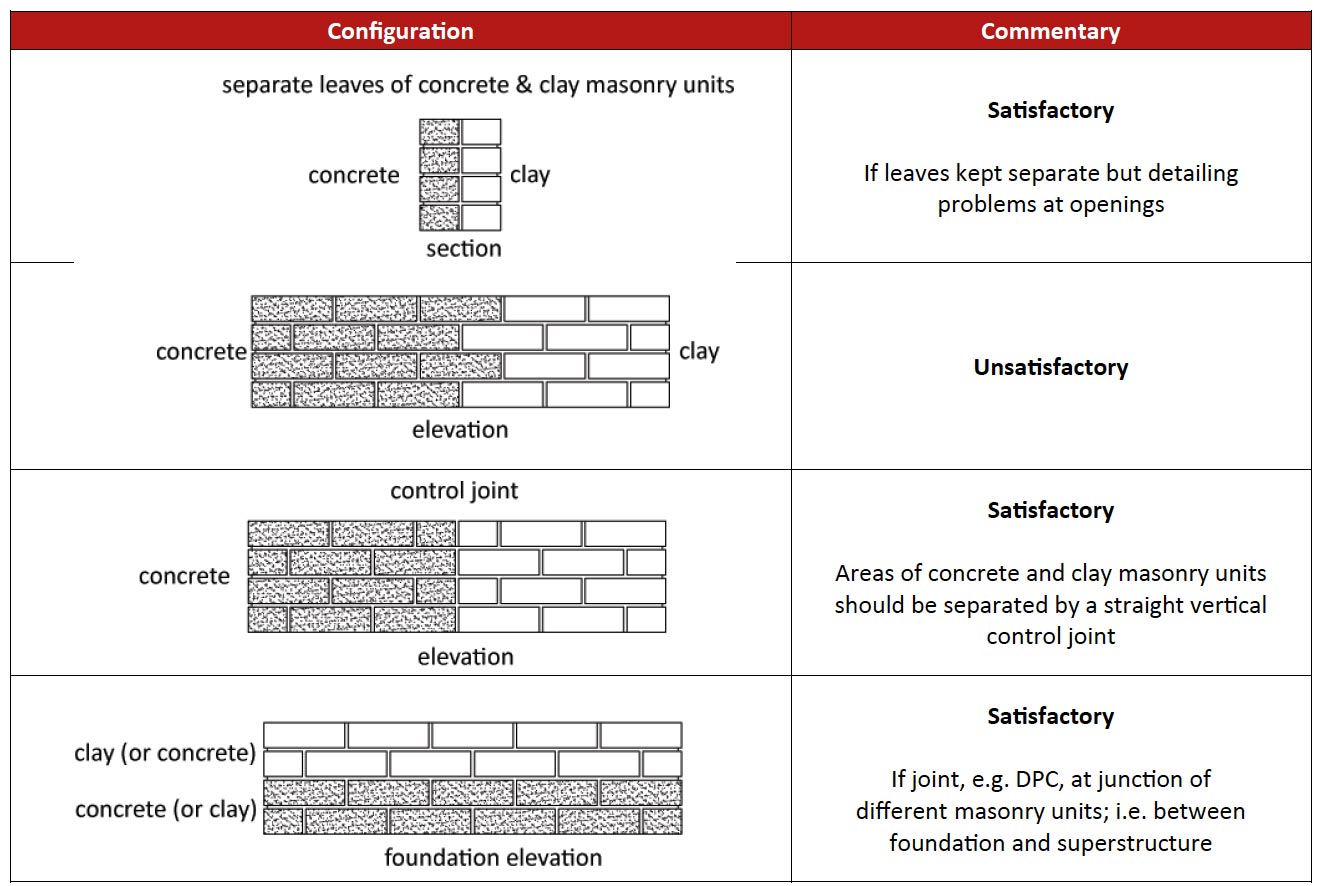
Figure 13.5 – Concrete and clay masonry units in the same wall
Calculating quantities
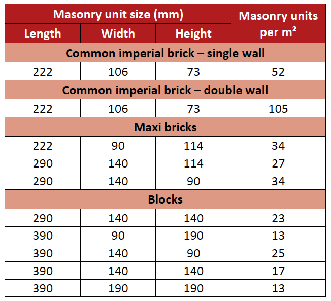
The table that follows provides the number of masonry units required per m² of wall for the most commonly used masonry units.
A figure of 10% is usually accepted when making allowance for wastage, which also includes for breakages (during offloading and construction). You would usually require 0.60m³ of mortar per 1000 bricks (standard stock brick) and because of bulking and waste, 1,0m³ of sand would be required for every 0,60m³ of mortar, i.e. 1m³ of sand per 1000 bricks.
Note: The table is based on exact sizes of solid masonry units, with 10 mm thick bedding and vertical joints, and no wastage (Quantities are rounded up).
Performance Criteria for Masonry
Outline
Not only must the quality of the masonry units be satisfactory, but the design, detailing, specification and workmanship must be of an appropriate standard. Any building should be designed to provide strength, stability, serviceability and durability in accordance with accepted principles of structural design. The design of the structural system of any building should be carried out in accordance with SABS 0160 (for loads) and SABS 0164 (for structural masonry).
However, “deemed-to-satisfy rules” for single and doublestorey buildings (with certain limitations) are covered in:
- SANS 10400 Part K: The Application of the National Building Regulations – (See extracts below)
- National Home Builders Registration Council’s Home Building Manual, parts 1, 2 and 3.
Empirical design (SANS 10400)
Building limitations
The building shall not exceed two storeys in height and shall be subject to the following limitations:
- The building plan-form and the layout of the intersecting, mutually stabilising walls that form part of such a building shall provide a structure that is stable against the action of horizontal forces from any direction and shall consist of rectangular, polygonal or circular cells, or a series of contiguous or intersecting cells.
- The span between supporting walls of a timber or metal roof truss, roof rafter or roof beam shall not exceed 10 m and the span between supporting walls of any first floor or roof slab shall not exceed 6m.
- The dead load of the roof covering material shall not exceed 800 N/m2 of slope area for roofs other than concrete slabs. Concrete roof slabs shall not exceed 175 mm in thickness if of solid construction, or the equivalent mass if of voided construction.
- Concrete first floor slabs shall not exceed 175 mm in thickness if of solid construction, or the equivalent mass if of voided construction.
- In order to limit floor loading on first floor space or on suspended ground floor slabs, the use of such floors shall be restricted to:
- detached dwelling houses and dwelling units;
- bedrooms, wards, dormitories, bathrooms containing soil fixtures, kitchens, dining rooms, lounges and corridors, in educational buildings, hospitals, hotels and other institutional occupancies;
- classrooms;
- offices; and
- cafes and restaurants
As a minimum the following performance criteria for masonry should be considered when designing buildings:
- Structural strength and stability of walls
- Water penetration
- Thermal insulation
- Sound insulation
- Fire resistance
Structural strength and stability of walls
Any wall shall be capable of safely sustaining any loads to which it is likely to be subjected and in the case of any structural wall such wall shall be capable of safely transferring such loads to the foundations supporting such wall. There is a wide range of structural considerations that may be required of a walling system, ranging from purely non-loadbearing cladding to the cellular masonry or concrete walling system which ultimately carries all the actions on a structure. These forces are illustrated in Fig 13.6. The thickness of the wall must be sufficient to carry such loads. The thickness must be in relation to the height of the wall and to prevent buckling and there must be adequate side support to resist overturning.
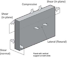
Figure 13.6 – Different loadings on a wall
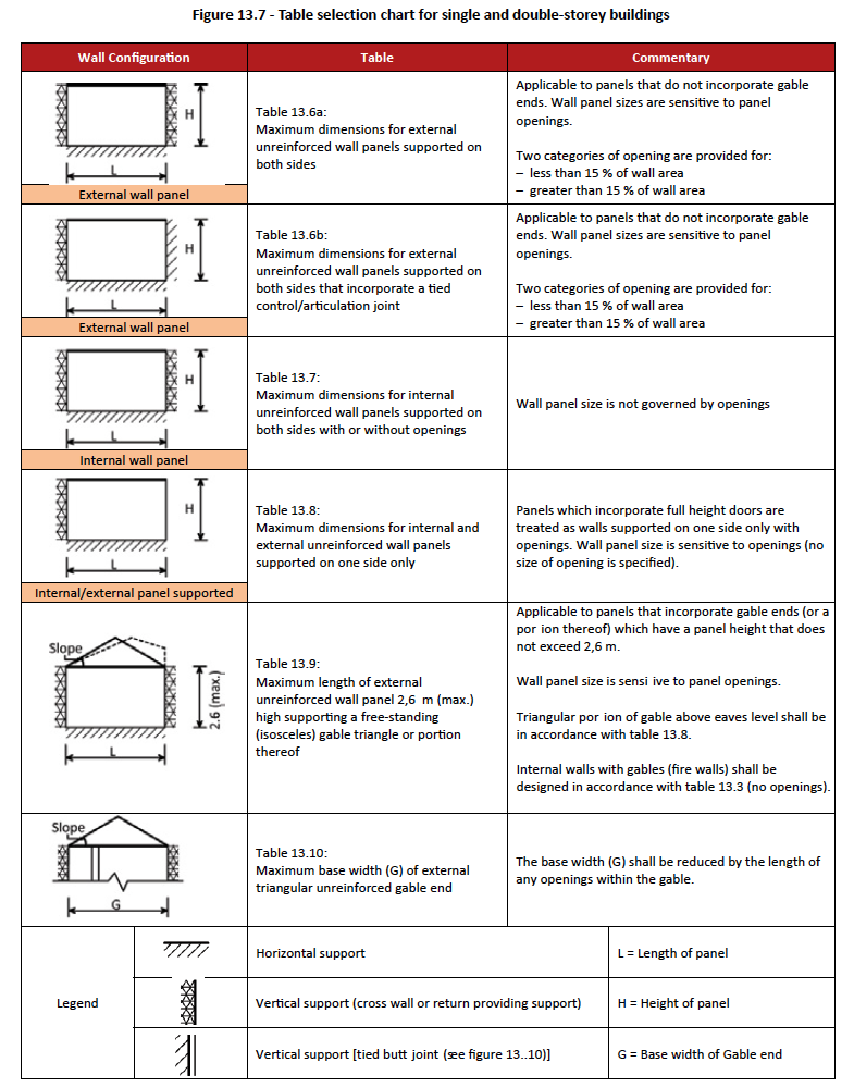
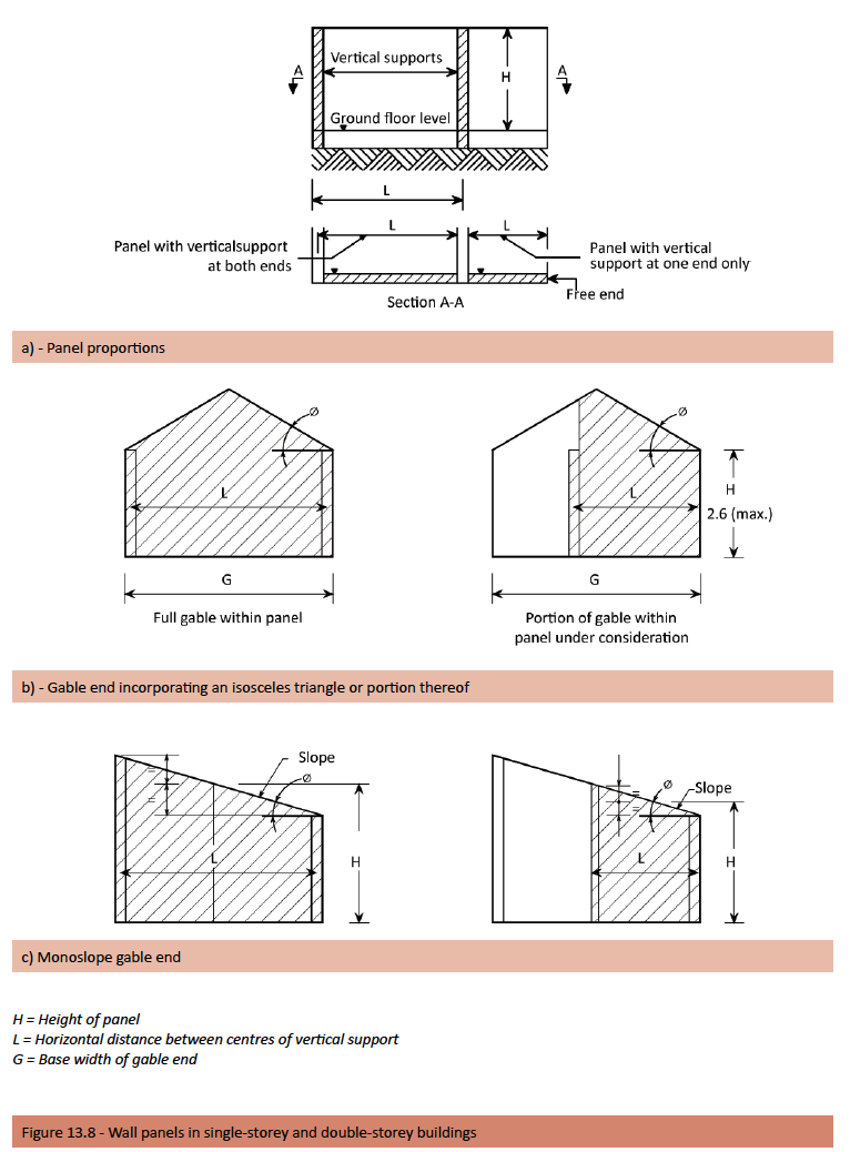
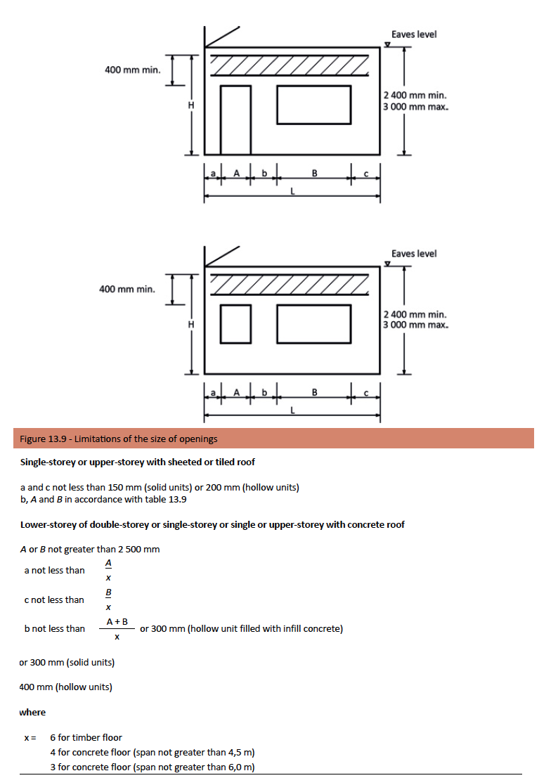
To illustrate this we include the following extracts from SANS 10400 Part K. – Masonry walling in single-storey and double-storey buildings.
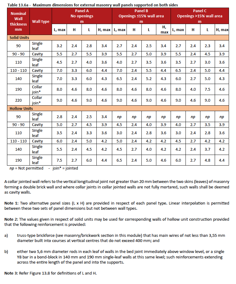
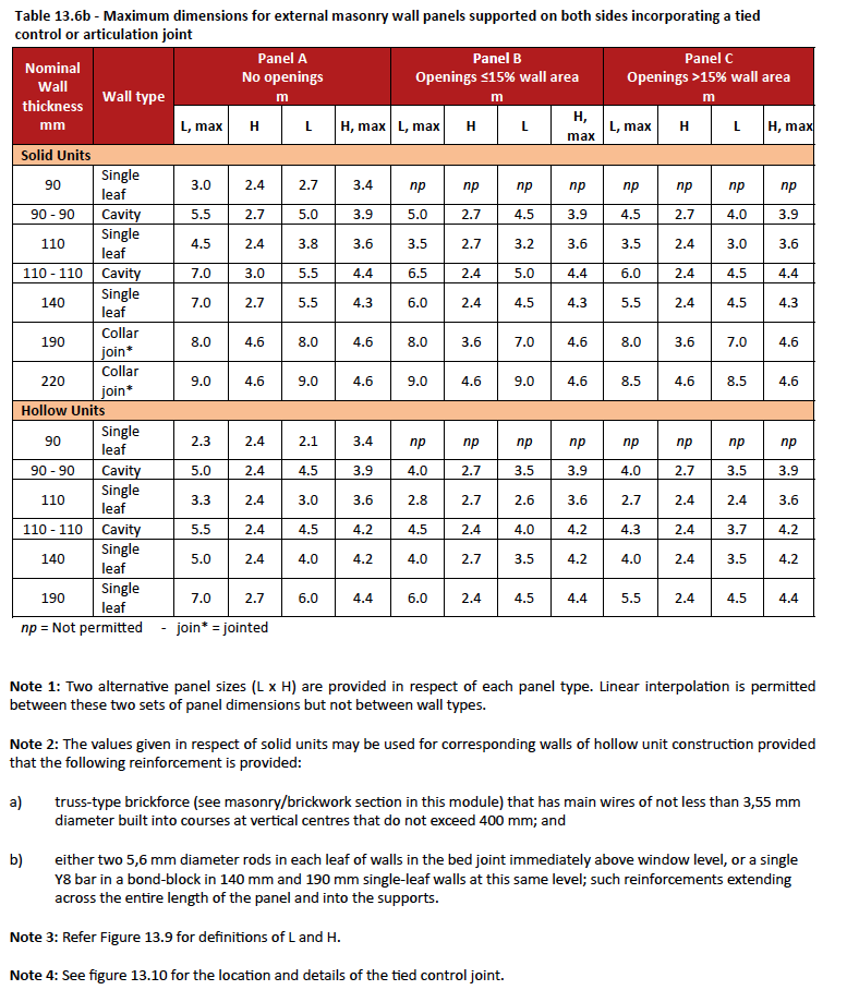
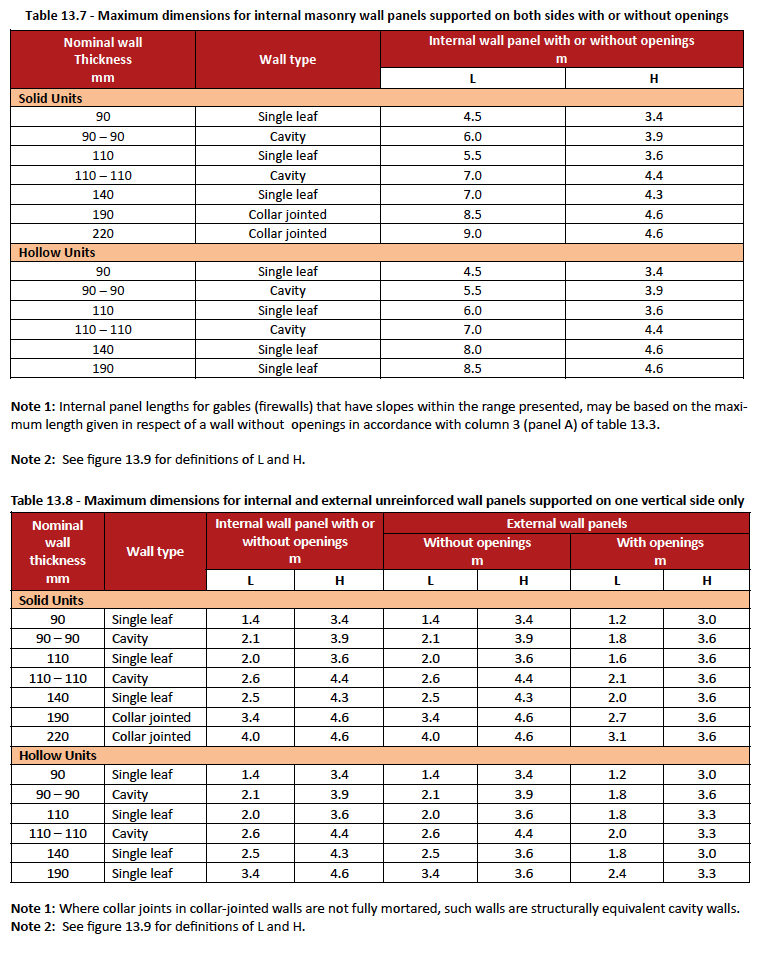
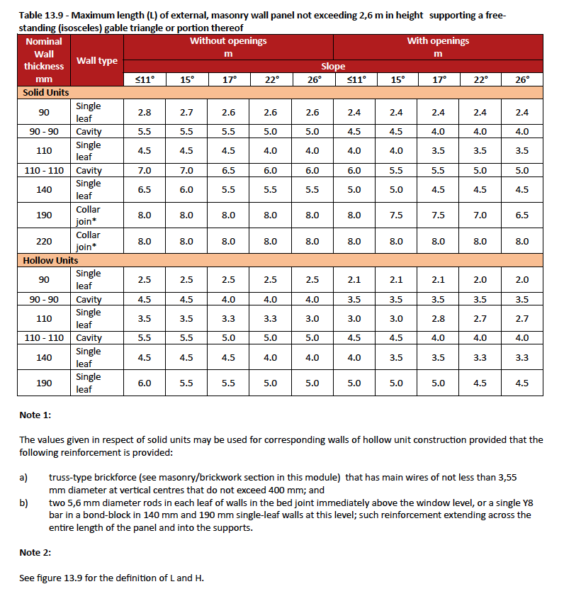
Masonry wall panels in single-storey and double-storey buildings shall have dimensions not greater than those derived from figures 13.7 and 13.8 and tables 13.3 to 10.8, subject to the maximum lengths of openings and the minimum distances between the faces of supports and openings and between successive openings being in accordance with figure 13.9 and table 13.9.
Note 1: The dimensions for panels with openings in tables 10.3, 10.4, 10.6 and 10.7 are only valid if lintels in accordance with the requirements of 4.2.9 are provided above all windows and openings.
Note 2: Occasionally, during the lifetime of a building, the positions of openings in walls are changed. For this reason, it is recommended that reinforcement be provided in a continuous band in external walls, particularly in the case of walls less than 190 mm thick, to form a lintel or “ring” beam.
Water penetration
Any wall shall be so constructed that it will adequately resist the penetration of water into any part of the building where it would be detrimental to the health of occupants or to the durability of such building.
Resistance to dampness
The penetration of any dampness to the interior of a building is one of the most common defects found in buildings today. Dampness can become hazardous and can cause early deterioration of the building and damage interior finishes and fittings.
Rising damp
Any wall or sleeper pier of a building shall be provided with damp-proofing and vapour barrier installations in such positions and to an extent that will reliably protect the wall against rising damp and the interior of the building against ingress of moisture from abutting ground.
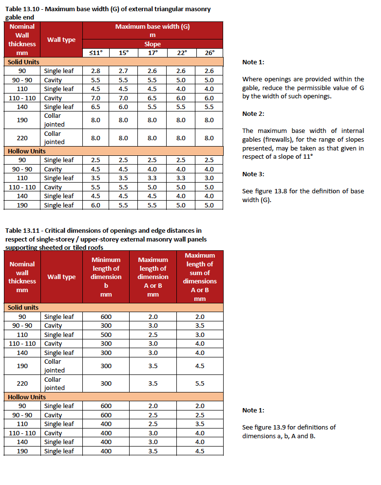
A damp-proof course (DPC) should be provided:
- In all external walls at level of the top of a concrete floor slab and 150mm above ground level
- Below any ground floor slab as appropriate to local conditions
- Below any ground floor timber beam or joist
- DPC shall be laid with mortar above and below the membrane. The membrane must extend over the full width of the wall including plaster thickness
- Overlaps at junctions, corners, etc. must be 150mm or greater.
- Where any wall of a room is below ground level, it shall be protected by a vertical DPC.
See Foundations – Damp proof membranes – Vertical damp proofing – for more information.
Any material used as a damp-proof course shall comply with the relevant requirements contained in SANS 48, SANS 98 or SANS 95, or be the subject of an Agrément certificate.
See Brickwork – Damp proof courses – for more information.
Weatherproofness
The resistance of a building to the ingress of rain depends not only upon the materials used, but on the quality of construction, skill of the designer and the work force, and on orientation, size and environmental exposure of the building. Water generally enters a wall through fine capillary passages at the interface between masonry unit and mortar or through cracks in the masonry caused by movement.
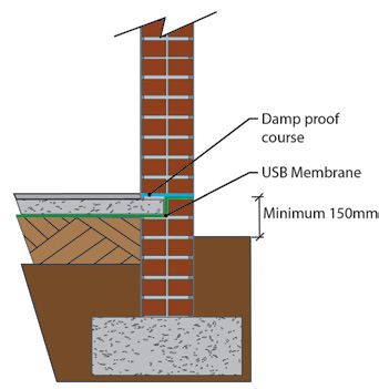
Figure 13.12 – DPC to external wall (Cavity wall)
Figure 13.12 – DPC to external wall (Cavity wall)
Prevention of rain penetration through walls begins with the design of the building, follows through with the selection of materials and the supervision of workmanship, and continues with maintenance of the structure after its completion.
The procedures to follow for exclusion of moisture from buildings are covered in detail in SANS 10249 and SANS 10021. Rain penetration of a wall can be determined by means of a rain penetration test described in SANS 10400-K. It has been found in practice that there is no simple correlation between permeability and porosity of a masonry unit and the performance of test panels using the same units of construction and subjected to the standard rain penetration test.
Single-leaf walls are more vulnerable to moisture penetration than cavity walls, where the air space provides an excellent barrier against the passage of moisture. Cavity wall construction should be used in coastal areas. If exposure conditions are severe, all non-cavity exterior walls should be plastered or given some other effective water-proofing coating. Alternatively, non-porous units should be used. The quality of the mortar and the workmanship requires particular attention if the structure is to be weatherproof. Specific recommendations on reducing rain penetration through walls and best results are obtained with:
- Cavity walls – cavities must be properly drained and ventilated.
- Provision of DPC’s and weepholes located where necessary.
- Providing correctly installed DPC’s.
- Non-continuous mortar bed across wall composed of hollow units, i.e. shell bedding.
- Correct profiles of joints; best – concave and vee joints, poorest – flush, struck and raked joints
- Correct detailing and reinforcing around windows and other openings to avoid cracks.
- Covering of top of walls – flashings, coping and roof overhang.
- Discharging of rainwater from roof run-off away from walls. Large roof overhangs best.
- Surface finish – rendering, plastering, and painting of non-face units and mortar.
- Provision of control joints, vertical and/or horizontal, of correct profile, spacing and sealing.
Thermal insulation
The thermal properties of any walling material are determined by how it handles heat, how heat transfers through it and how well it holds or stores heat. Heat always moves from warm to cold, so in summer with the outside temperature warmer than the inside, the heat transfers into the building through the walls from the outside and vice versa in winter. Masonry is naturally thermally efficient and these thermal properties of masonry units differ from type to type depending upon the materials of manufacture, profile, mass and density; and when used in conjunction with cavity wall construction it has the effect of ensuring that buildings stay warmer in winter and cooler in summer, which can be made even more efficient with the installation of an insulation material in the cavity.
To better understand the thermal properties of walling it is necessary to know the following:
- Thermal transmittance, (U value) is measured in Watts (W) per square metre (m2) per degree Celsius, W/m2 °C as the rate of heat flow through an element e.g. a wall. The lower the U value, the better the insulation properties of the wall: it has a greater resistance to the flow of heat. The U value not only takes into account the resistance offered by the wall, but also the outside and inside surface resistance. Since the U value notionally provides a measure of the heat flow through a wall, it is the figure used to compare the performance of different constructions and to make energy-use calculations.
- Thermal capacity is measured in Joules (J) per square metre (m2) per degree Celsius, J/m2 °C, and is a measure of the degree of heat that can be stored by a wall. Clay brick walls, with their high thermal capacity, have the ability to store heat during the day and release this heat at night (commonly referred to as thermal mass). In climatic regions where there are high temperatures during the day and low temperatures at night, this results in thermally comfortable dwellings with a reduction in energy consumption to cool or heat the buildings.
All the materials of a wall, including any window openings, and even the spaces between layers of the materials (cavities), contribute to its thermal performance. The contribution of the different elements is assessed by testing (more especially for commercial buildings), but for many purposes values are rounded to standardised published values which are used in calculations e.g. for determining heat loads for air-conditioning systems.
What is important is where that insulation goes within the wall, that it is laid consistently, filling every space and avoiding thermal bridges, and that it is located on the correct side of any item of construction, which functions as a vapour control layer.
See Brickwork – Cavity walls – Installing thermal insulation – for more information
Extracts from SANS 204
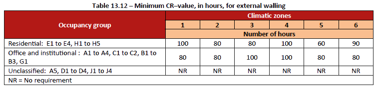
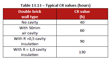
Masonry walls such as, but not limited to, cavity, grouted cavity, diaphragm, collar-jointed and single leaf masonry, shall achieve the minimum CR-value given in table 10.10 [see next page] for the different types of occupancies in the different climatic zones (see Climatic Zones in Foundation section page 53). CR product requirements and their application are here for reference purposes only. They do not form part of the discussed SANS 204 standard.
Note: The CR product of a walling system is calculated from first principles
C (thermal capacity) = total of all layers in the wall system, with each layers capacity calculated as: Specific heat (kJ/ Kg.k) x thickness (m) x density (Kg/m3) = C (kJ/m2.k)
R (Thermal resistance) = total of all layers in the wall system, with each layers resistance calculated as: Thickness (m) / thermal conductivity (W/m.k) = R (m2.k/W)
C x R = kJ/m2.k x m2.k/W = kJ/W =Kiloseconds
Multiplying by 100/3600 provides a CR product value in hours.
For the CR-values of walls, contact the relevant manufacturer/s.
Table 13.13 provides typical values for double brick masonry walls, with or without additional insulation.Thermal resistance that is added to external walling with high thermal capacity, should be placed in between layers e.g. in the cavity of a masonry wall. Thermal resistance should not be added to the internal face of a wall with high thermal capacity.
Designers should consider that interstitial condensation occurs in walling systems which are not able to prevent or accommodate moisture migration. The selection of vapour barriers and appropriate construction materials, including insulation, is important for the thermal efficiency of walling in climate zones where damp and high relative humidity is experienced.
Sound insulation
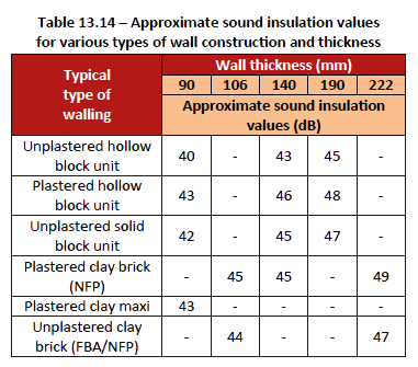
Sound (acoustic) insulation, measured in decibels (dB), is the ability of a wall to resist the transmission of airborne sound. The measurement is based on a logarithmic scale and is not linear, which implies that halving or doubling of insulation value would be represented by a 6dB change. Masonry is a suitable material for attenuating noise as it is a dense material which reduces the transmission of airborne sound. Resistance to sound transmission increases with wall thickness (see Table 13.14).
Surface texture, porosity and density all affect the transmission and absorption of sound. The sound insulation properties of a single-leaf masonry wall are largely related to the mass per unit area of wall provided there are no direct air passages through the wall. The sound insulation properties of a cavity wall are related to its mass per unit area, the width of the cavity and the rigidity and spacing of the wall ties. At present there is no sound insulation or acoustic performance criteria provided for in the National Building Regulations.
Fire resistance
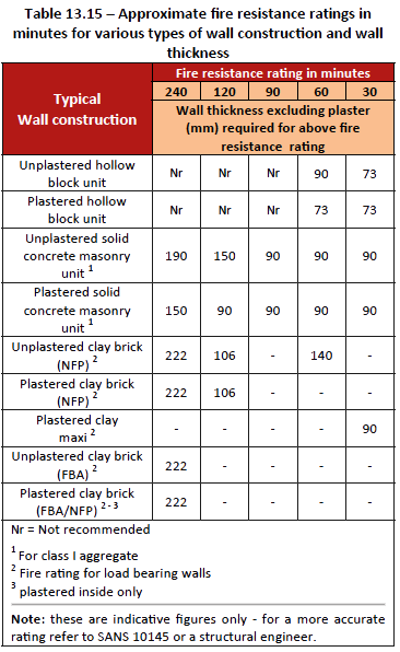
Fire resistance rating is a measure of the length of time a walling element will resist a fully developed fire. Failure occurs in an element when its resistance is overcome in a defined way. Firstly, if it collapses or its structural ability is impaired, it is said to have failed at the time of collapse. Secondly, a wall can fail if it develops cracks and fissures through which hot gas or flame can pass and, thirdly, an element can fail if the temperature on the side away from the fire exceeds a certain level.
The fire resistance rating of masonry walls depends on whether the wall is load-bearing or not, whether solid or hollow masonry units are used and on the geological type of the aggregates used in the manufacture of the units.
Note: Plastering the wall improves the fire resistance rating.
The National Building Regulations requirements for walls are covered in SANS 10400-K. The fire resistance ratings of masonry walls are given in SANS 10145.
Different criteria apply to different building types, heights of walls and the relative position of the wall within the building and to the boundary of the site. Both the resistance to the spread of fire within the building and to adjacent buildings, and the ability of the wall to withstand fire are covered in the supporting documents of the national building regulations. All external walls must be fire-resisting to some degree, which may limit options particularly in respect of openings and their construction, but residential buildings are allowed different limits from other building types.
Retaining walls
Retaining walls are required where there is a difference in levels. The retaining wall is positioned between the two different levels and retains the soil below the higher level. The wall can be constructed of reinforced concrete or brickwork or a combination of the two.
Free-standing retaining walls should be designed and constructed so that:
- the height of fill retained by free-standing retaining walls (see figure 13.16) does not exceed the values given in table 13.14, provided, however, that where x (see figure 13.13) exceeds 0,3 m, the height retained is reduced by the difference between x and 0,3 m,
- piers, where required in terms of table 13.16, project on the opposite side of the wall to the fill that is being retained, • control joints are located at intervals that do not exceed 10 m,
- no surcharge of fill is placed within a distance equal to the height of the amount of fill being retained, and
- Subsoil drainage is provided behind the wall by providing weep-holes formed by building into the wall, 50 mm diameter plastic pipes, with the non-exposed end cut into the perforated pipe installed behind the retaining wall at the bottom of the filling covered with geo-fabric and coarse aggregate, at a height that does not exceed 300 mm above the lower ground level, at centres that do not exceed 1,5 m. Allowing water to pass through the aggregate and geo-fabric, and into the pipes that will exit on the exterior of the wall. The purpose of the agricultural/subsoil drain is to reduce as much water pressure as possible behind the retaining wall.
See foundation section – back filling for details on foundation walls where fill is retained behind the foundation wall.
An engineer usually designs a reinforced concrete retaining wall. However, a free-standing retaining wall built in accordance with table 13.16 and figure 13.13 can be constructed without using an engineer.
Small free-standing retaining walls are used to support slopes steeper than those at which they would be naturally stable. Typical uses are to provide flat terraces in a sloping site for gardens or access paths. Small is defined here as a height typically up to 1.5m or occasionally 2.0m. Any retaining walls higher than 1.8m reinforced or unreinforced must be designed by an engineer.
Retaining walls are normally specifically designed for each separate application and fall into the following categories:
- gravity walls,
- reinforced walls on spread foundations,
- embedded walls, which may be anchored, propped or cantilevered,
- gabions and cribs.
See – The Site Work Section for more detailed information on retaining walls.
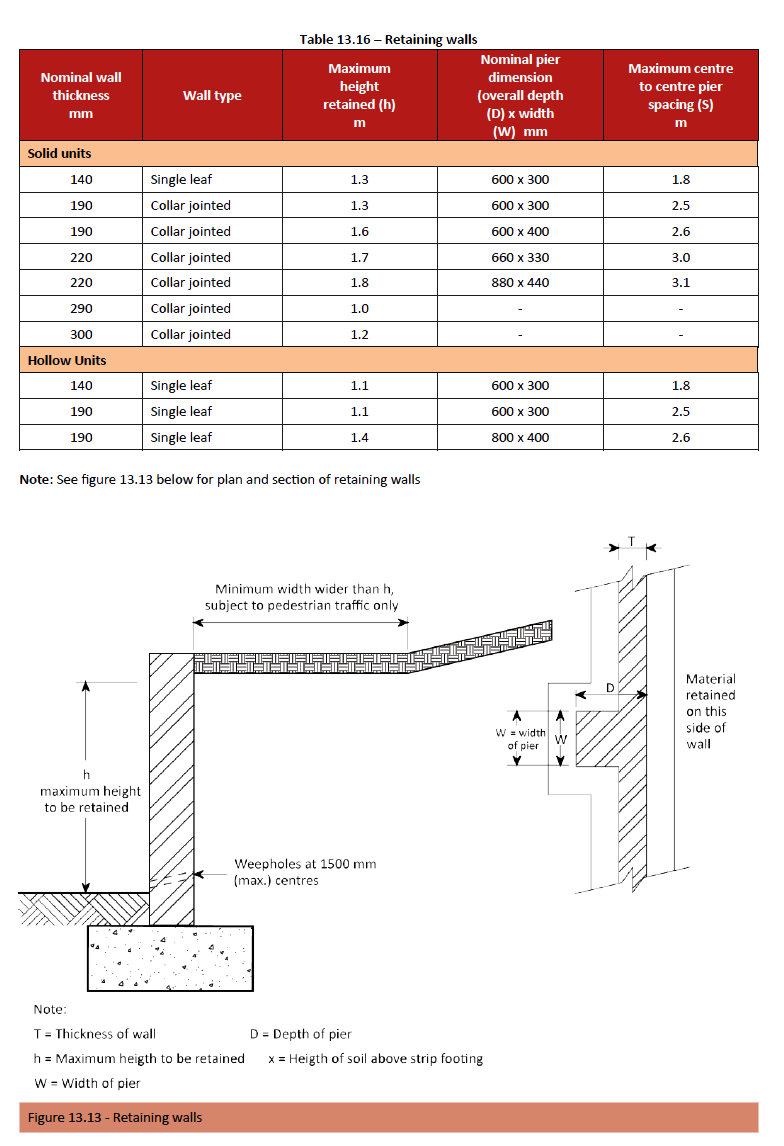
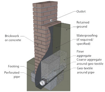
Figure-13.14
Window and door frames
Outline
Windows and doors so far as possible, should not compromise the main performance requirements selected for the walls in which they are to be incorporated. Nevertheless, any puncturing of the external wall carries with it a risk of reduced overall performance with respect to one or more of the following;
- strength and stability,
- weather exclusion,
- fire resistance,
- general safety issues including security, and
- thermal and sound insulation
Window frames
Windows have two prime purposes:
- the admission of daylight and sunlight, and
- the admission and emission of air needed for ventilation purposes
A window has an outer frame, a sash (the opening part) and its glazing. A sash is defined as a surround for glazing; it fits into the window frame and can be hinged, sliding or fixed.
- A sash window is a frame with two sashes that open by sliding vertically. Both have sash balances or traditional sash weights so that the sashes are easy to push up and stay in position at any height.
- A horizontally sliding sash window is a sliding window.
- A hinged sash window is a casement type window; side hung or top hung.
One can choose between full pane and small pane. Added to the above is the advancements made in glazing, which again gives you a large variety in choice of finish. Thermal and insulation properties are becoming more important as energy saving becomes a real problem worldwide; a lot of heat or cooling is lost through the windows, not only in the frame but more particularly in the glazing.
Windows are therefore to be considered as efficient transmitters of solar radiation but as poor insulators unless glazed effectively and fitted correctly. Windows are manufactured from a number of different materials, all having their own specific advantages. One must remember there are different qualities of manufacture, which is discussed below in greater detail under each specific manufacturing type.
Door frames
The prime purpose of a door is:
- To provide an entry and exit point to a building for occupants and goods.
A door frame can be defined as a surround in which a door leaf is hung or slides, and usually made of timber/wood, pressed metal or aluminium.
Hanging door frames usually have two jambs and a head about 100 x 80mm and rebated either as single or double to receive a door or a pair of doors.
Besides the traditional single leaf swing door there are double, pivot, sliding, folding, concertina and French doors. Some sliding and folding door frames are specifically manufactured for the type of door required, and include purpose made bottom and top rails depending on the location of the frame (inside or outside) and the type of manufacture itself e.g. timber or aluminium.
The bottom rail is the most important detail as a functional part of the fabrication of the frame, for the way the doors slide or fold i.e. to the outside or inside, left or right and at the same time acting as a weather guard or seal from the elements, be it wind, rain or both.
Side hung swing frames are usually stood up in position, plumbed (a right angles) and braced before bricklaying is started and built in as work proceeds or progresses by means of lugs fitted to the frame, which are built into the brickwork (the mortar joint). See – The superstructure process – positioning doors – for more single or double leaf frames differ in dimensions and design depending on what material they are made of and size of section or profile used. The standard rebate size for door frames is ±46mm as most door leafs are manufactured to a nominal thickness of 44mm.
Types
Steel
Window frames
Steel has been the most commonly used material in the manufacture of windows in the past and has remained one of the oldest forms of manufacture. Years ago, all the steel window manufacturers in South Africa, got together to standardize their products. Now every steel window manufactured has the same product code, same size of manufacture, no matter who the manufacturer is. Residential windows are available in either an affordable light duty F7 section, or manufactured in accordance to SABS specifications in FX7. All frames are coated as part of the manufacturing process in a one shop coat red oxide primer or available as hot dip galvanized or pre-galvanized.
Steel sashes come in three standard variations:
- Side hung/Residential open out – full pane and small pane
- Top hung/Awning type
- Industrial type
A range of coupling mullions and transoms are available for combining standard windows to form composite units. Also available are semi heads which can be coupled above standard windows.
Frames are supplied with handles, hinges and stays (furniture), all in mild steel with the handles and stays being plated brass, which can be specified to include solid brass or chromium plated fittings.
Glazing is done after the frame is fitted, using putty, and usually after all the wet trades have been completed, and in accordance with SANS 10137 code of practice.
There are new generation steel products available that use glazing beads with rubber gaskets similar to that of aluminium windows. Steel frames are fitted with lugs and are generally built-in during construction and are not fitted after completion of the brickwork or plastering. Steel frames have to be painted once glazed, generally using a primer and top/final coat.
Steel frames require maintenance. Three factors contribute to the intervals of maintenance required; the quality of coatings used the geographical location and exposure to the sun i.e. west or south facing. Steel window frames are regarded as the strongest and are more robust than for example wooden frames, especially when it comes to the fitment of burglar proofing.
Door frames
Standard Steel frames are manufactured from pressed metal, available as hot dip galvanized, pre- galvanized or with one shop coat red oxide primer. And available in three different qualities:
- HD – Standard heavy duty door frame – metal thickness 1.6mm
- LD – Light duty door frame – metal thickness 1.0mm (these frames are not recommended for external doors)
- E – Economy door frame – metal thickness 0.6 to 0.8mm (these frames are not recommended)
- To provide an entry and exit point to a building for occupants and goods.
Windows are therefore to be considered as efficient transmitters of solar radiation but as poor insulators unless glazed effectively and fitted correctly. Windows are manufactured from a number of different materials, all having their own specific advantages. One must remember there are different qualities of manufacture, which is discussed below in greater detail under each specific manufacturing type.
Door frames
The prime purpose of a door is:
A door frame can be defined as a surround in which a door leaf is hung or slides, and usually made of timber/wood, pressed metal or aluminium.
Hanging door frames usually have two jambs and a head about 100 x 80mm and rebated either as single or double to receive a door or a pair of doors.
Besides the traditional single leaf swing door there are double, pivot, sliding, folding, concertina and French doors. Some sliding and folding door frames are specifically manufactured for the type of door required, and include purpose made bottom and top rails depending on the location of the frame (inside or outside) and the type of manufacture itself e.g. timber or aluminium.
The bottom rail is the most important detail as a functional part of the fabrication of the frame, for the way the doors slide or fold i.e. to the outside or inside, left or right and at the same time acting as a weather guard or seal from the elements, be it wind, rain or both.
Side hung swing frames are usually stood up in position, plumbed (a right angles) and braced before bricklaying is started and built in as work proceeds or progresses by means of lugs fitted to the frame, which are built into the brickwork (the mortar joint). See – The superstructure process – positioning doors – for more single or double leaf frames differ in dimensions and design depending on what material they are made of and size of section or profile used. The standard rebate size for door frames is ±46mm as most door leafs are manufactured to a nominal thickness of 44mm.
Timber
Window frames
Window frames
Timber, also known as wooden windows have been in existence for hundreds of years, made from a variety of different types of wood. The most commonly used timber in the manufacture of wooden windows in South Africa is meranti; meranti is a collective name of sub-tropical hardwoods from Indonesia and Malaysia.
However due to uncontrolled harvesting; these rainforests are nearly depleted almost beyond recovery, which results in an unreliable supply of resource. Some manufactures are therefore using other timbers like Okoumé which comes from Gabon-West Africa.
Timber is a product of nature which reacts to moisture and climatic changes; hence the importance of the kiln drying process, in the quality of the timber used in the manufacturing process of windows. It is recommended timber be Kiln dried to a specific percentage i.e. 8% to 15% which is the ideal moisture content for our climate. The difference in the moisture content in inland areas is taken into account when manufacturing. It keeps the wood in perfect balance with atmospheric conditions, thereby minimizing any movement or warping.
Timber frames are very good insulators but require more maintenance than other frame types. Timber frames may also require larger tolerances in openings which can result in gaps that allow air leakage, unless good draught sealing (weather-stripping) is provided; and excessive air leakage can be further dependent on the quality of frame (timber used and manufacture). The inclusion of rubber seals on all windows and selected doors reduces air leakage. The quality of wooden windows is not only based on the timber selected as described above, but also the colour consistency of the timber used is important.
Timber sashes come in four standard variations:
- Side hung/Casement type – Full pane and small pane
- Top hung/Awning type
- Vertical sliding sash – Full pane and small pane
- Mock Sash – Full pane and small pane
All wooden windows must be sealed prior to installation, which includes the top, bottom and sides of the frame, preventing moisture from entering the wood. If any part of the window is cut or drilled, the exposed area should be treated/sealed immediately. Timber stains very easily if not sealed and can be burnt by mortar or plaster, leaving the frame discoloured. Frames are supplied with handles, hinges and stays (furniture) and depending on the quality of manufacture it could be that the furniture is brass plated, solid brass or heavy solid brass. Glazing is done after the frame is fitted using putty or a combination of putty and timber glazing beads, and usually after all the wet trades have been completed, and in accordance with SANS 10137 code of practice.
Wooden frames are generally built in during construction, using galvanized hoop iron or wire nails as lugs. Frames can also be fitted after completion of the brickwork commonly then termed as “second fix” frames. Frames need to be painted/sealed after they are built in. Even with the timber having been carefully selected and kiln dried properly, it is still subject to climatic change, due to variations in humidity and temperature and it is therefore important that frames are sealed to protect them against moisture penetration, UV and other weather conditions.
Wooden frames need regular maintenance, which can also depend on the choice of sealant or varnish used, the geographical location and exposure to the sun, i.e. west or south facing. Burglar proofing is not as effective because in most cases the burglar bars are retro fitted and screwed into the frame. With some manufacturers, the bars are made specially to penetrate into the window frame for added strength and protection, which can be done when ordering frames with fitted burglar bars. In the case of cottage or small pane windows some manufacturers actually have a steel core within the timber sections of these small panes installed.
Door frames
Timber door frames are manufactured from the same materials as described above and share the same properties. Frames are manufactured in a myriad of different overall frame size, thicknesses, qualities and shapes and where only the actual door sizes are somewhat standardized regardless of the producer.
Aluminium
Window frames
Window frames
Aluminium is a widely-used frame material in South Africa. Aluminium frames are light, strong, durable and easily extruded into complex shapes. Aluminium is a good conductor of heat (i.e. a poor insulator) and thus, aluminium frames need to incorporate a ‘thermal break’ a plastic insert, inserted between frame sections to reduce the amount of heat that is transmitted through the frame. Aluminium can be powder coated in a variety of colours, that don’t fade, in a way that enhances the corrosion and abrasion resistance of the metal. Anodized windows are chemically stained, leaving a metallic finish in either natural or bronze.
Standard sizes are available from a number of manufacturers or fabricators, and special sizes are made after measuring on site, which is considered quite normal in this form of manufacture
. Aluminium sashes come in four typical variations:
- Projected top hung coded PT
- Projected side hung coded PS
- Vertical sliding coded VS
- Horizontal sliding coded
SW PT or PS denotes 1(one) opening and PTT or PSS denotes 2 (two) openings A range of coupling mullions and transoms to suit various spans is available for combining standard windows to form composite units.
In almost all cases aluminium frames are fitted after the brickwork is completed and before the plaster is completed to the window soffits and reveals, commonly known as ‘second-fix’ or ‘retro – fitted’ frames. If sub-frames are used, frames can be installed after all wet trades are complete to prevent damage.
Windows are fitted in various ways; with lugs, screws and plugs or Hilti nails, depending upon specific details and the project. All windows are factory glazed with glazing gaskets (rubber seal) before installation and in accordance with SANS 10137 code of practice.
All windows are supplied with friction stays, hinges and handles (furniture). Some manufacturers have different qualities of furniture available; including various options, depending upon the application. Aluminium needs little maintenance, it does not need to be painted, but does oxidize (similar to rust) over time and should therefore be kept clean using soap and water. Depending upon the geographical location, cleaning will need to be done on a more regular basis .e.g. within 3kms from the sea.
Aluminium is very soft and can easily be damaged. Care must be given when frames have been installed, especially when wet trades are not complete. Frames are protected in plastic once installed but this does not prevent careless damage, furthermore coatings can be scratched if sufficient care is not taken, when cleaning frames after plastering; which can be very difficult to repair afterwards.
Burglar bars are optional and available as an integrated part of the frame.
Door frames
In simple terms an aluminium door frame can be fabricated to suit all types of door leafs and yet side hung aluminium frames are seldom used in domestic/residential building applications and are more commonly used in commercial applications, and more particularly in dry walling.
Aluminium Doors &; Frames as one composite unit are used extensively in residential buildings as well as in commercial applications, for example sliding and folding doors.
uPVC
uPVC was first used as a window material in Europe 60 years ago and is nowadays by far the most common window and door material in use in Europe. The use of uPVC has now spread to most parts of the world. The last couple of years has seen a rapid increase in the use of uPVC as a window and door material here in South Africa as well, owing to a number of reasons.
The unique thermal qualities of the multi-chambered frames of uPVC windows and doors result in easy achievement of compliance to SANS 204 and SANS 10400. Furthermore the rising cost of energy and an increased awareness of environmental issues has made uPVC very popular. uPVC Frames are fabricated with a purpose-made sealed reinforcing chamber where galvanised steel is inserted to create a ridged and strong frame. The outer frame and sashes are heat welded to form a strong weather proof frame. The sash and glazing sections are sealed with purpose-made multiple sealed gaskets which provide a weather resistant and dust proof environment.
The glazing rebate can accommodate either single glazing, double glazing or even triple glazing making the system very versatile, reducing heat loss and decreasing external noise. uPVC has a low carbon footprint and is easily recycled.
uPVC windows can be provided with a wide range of hardware options from simple cockspur handles to high security multipoint built-in locks. The windows have a smooth finish, are easy to clean and maintain. They won‘t rot, warp or corrode and never need re-painting or coating. The only maintenance required is an occasional wipe down and lubrication of the locks.
UPVC windows and doors are available in a variety of opening combinations including:
Windows
- Open out casement systems
- Open in tilt and turn systems
- Horizontal sliding
- Fire-rated systems
Doors
- Sliding two, three, four and 6 part sliding.
- Single and double (French) open in and out doors
- Multi fold doors
- Stable doors. uPVC is available in a number of finishes such as:
- Standard white
- Woodgrain foil
- Painted colour application.
However, not all the uPVC available in South Africa is UV stable and could become effected by the harsh weather conditions and high level of UV rays in Southern Africa. The following is a guide on what to look out for when buying or specifying UPVC:
- The profile is UV stable and carries a warrantee to prove this.
- The profile is tested to and conforms to SABS 1553-1 2007.
- The profile is is manufactured in a plant that has ISO 9001 and 14001 certification.
- The profile is tested to and conforms with BS EN 12608.
- The profile has undergone hot box thermal testing with verifiable thermal results.
- The profile system company is a member of AAAMSA.
- The fabricator has been trained and is approved to install the window system.
Adherence to the above will ensure a quality, durable end product.
Sizes and categories
Window frames
Window frames are fabricated in the types as described above and by a number of different manufacturers. Generally the sizes of window frames are similar in width and height but are seldom fabricated by different manufacturers with identical dimensions except for Steel frames. The format or modules of the widths and heights of standard window frames can be best described in the following table:
Door frames
Steel
Steel
Sizes shown on the following page are taken from the rebate at the head of the frame to the finished floor level. All rebates are manufactured to suite a 44mm nominal door thickness. Available as left or right hand frames, as the hinges are factory fitted. Whether inward or outward opening, the “hand” of a single door should be determined by the side on which the hinges are fitted, when viewed from the hinge side. See figure 13.16.
Steel Frames are available for the following common wall thicknesses 115mm, 150mm and 230mm.
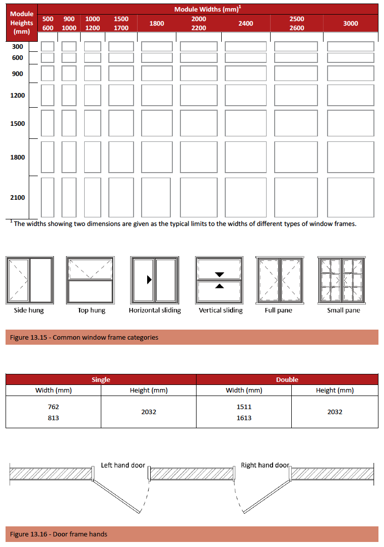
Timber
Timber frames are available in the following typical sizes inside the rebate (the door size); the variation in (section) size and how it impacts the overall width of the frame are also shown.
- Interior timber jambliner frames are available in widths of 110-115mm, 140-150mm and 240-250mm.
- Aluminium and uPVC door frames are manufactured in the categories as illustrated above although only in limited variations and are seldom used in residential buildings.
Sliding doors
Sliding doors are doors that slide sideways (horizontally); usually having an overhead track and floor guide that suits the location of the door i.e. internal or external. Sliding doors are available in different sizes and can be used in conjunction with sidelights and toplights which are also available in a number of variations. Two Panel doors are available with the left or right side panel sliding.
Sliding doors are available in variations of the following widths depending on the type of manufacture: 1.500 – 1.800 – 2.100 – 2.400 – 2.700 – 3.000 – 3.600 – 4.200 – 4.800 (mm)
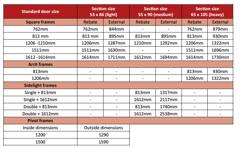
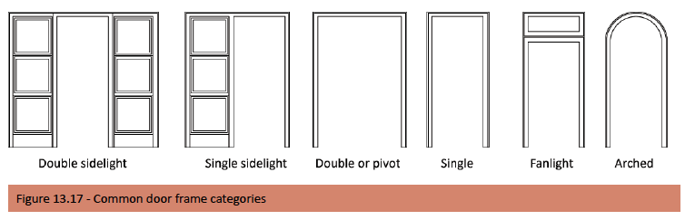
Other Structural Forms
Outline
With fast developing new technologies and ever increasing building costs, the need to erect structures at greater speeds is becoming more and more important.
Structural steel portal frames have been used for many years in the industrial building sector and are now becoming a viable option in the residential sector. Another structural form that has been used for hundreds of years in multi storey buildings is reinforced concrete and is used in combination with structural steel daily; the reinforced concrete used for the foundations and slabs while structural steel is used for the superstructure.
Reinforced concrete frame
A reinforced concrete frame is basically a combination of a number of reinforced concrete columns and beams all joined together to create a concrete frame. Reinforced concrete has reinforcing steel in addition to the plain concrete mass. Steel or reinforcing steel is strong in tension. The combination of concrete and steel increases the ability of a member or members to carry additional loads. And advantage is that the size of the members can be reduced due to the extra strength provided by the steel.
Structural steel
Structural steel is composed almost entirely of iron with small quantities of other elements added to give it strength and ductility. Using structural steel in building construction began at the beginning of the 20th century and gained popularity in the construction of small-to-medium span industrial buildings. As with reinforced concrete, the elements of the building (the columns and beams) remain the same, but are replaced by structural steel members, commonly referred to as steel portal frames, trusses, girders etc.
A portal frame structure consists of a series of steel beams and columns that are connected in such a way that they form and arch. This creates large clear working arrears inside a building.
Structural steel frames are easily assembled and erected. They are relatively cheap compared to reinforced concrete and are not very labour intensive. The speed of manufacture, transport and erection also make steel a desirable material for certain types of structural forms.
Portal frames can also be made using precast concrete elements.
Precast and fabricated forms
Concrete
The overall concept of precast concrete is the same as those of reinforced concrete and structural steel. Most precast concrete frames are produced as part of a ‘system’ building, where the various parts or elements are slotted together to complete the product.
Fabricated
There is a move toward having building components or products other than concrete designed and fabricated as a ‘system’ in a factory, then delivered to site and put together to form a structure or home as one complete unit. As done in the USA.
Although there is resistance to this form of construction in South Africa, it is something that will eventually need to be embraced by the consumer in order to fulfil our housing demand.
Note: See Section 11, Alternative Building Methods, for more information
Concrete Slabs
Outline
Suspended concrete slabs for floors and roofs have been part of construction since the advent of Portland cement in the 1820s. In situ concrete (reinforced concrete) slabs (floors) have been the most commonly used method in the past.
However with the overall consideration of reducing building costs and increasing efficiency over the last few decades, alternative methods or systems of constructing suspended concrete floor slabs has developed.
Note: All types of suspended concrete slabs used in South Africa have to be designed by a professional Engineer.
Types
In situ- reinforced concrete (RC) slab
A concrete slab, including the beams or columns that have formwork; temporary or permanent into which concrete is poured, keeping it in place until it cures. Typically designed by an Engineer; cast with this is the steel reinforcement which is necessary to provide the strength required; which too would be specified by the Engineer.
These types of slabs are normally used in applications where greater spans or loads or both are required; for example, in multi storey buildings. Also used when difficult shapes need to be cast, like staircases, or if longer cantilever projection is required
Hollow-core (HC) slab
A reinforced or pre-stressed concrete slab designed as a ribbed slab, containing cores; generally varying in thickness from 120mm to 250mm and depending on loading, spanning up to 12m. The width is normally .900 or 1.200m
Cores are typically either circular or elliptical. Hollow cores afford a reduction in self-weight of 30% or more, compared with a solid slab of the same depth. For most applications, no propping is necessary during construction, but crane access is essential.
Hollow-core concrete slabs are finding increasing favour as a means of fast-tracking the construction of medium-rise buildings in South Africa. Unlike in Europe and North America where it is the default system for such structures, the technology has been a slow-starter in SA, owing mainly to the conservative approach adopted by the local engineering fraternity. However, time delays and rising costs attendant on in-situ casting make precast flooring a more attractive proposition with certain projects.
Rib and block (RB) slab
Composed of rectangular shaped precast concrete reinforced or pre-stressed ribs, supporting rebated non-structural hollow concrete or EPS filler blocks placed between two ribs; the most common rib spacing being 560, 600 and 650mm. This system is sometimes referred to as plank and block or beam and block.
A structural concrete topping is poured between and over the blocks; with a minimum thickness of 40mm. Steel reinforcing is placed in the voids above the ribs to stiffen the slab and welded mesh reinforcement is placed in this topping to control possible shrinkage cracks.
The filler blocks are available in different heights ranging from 120mm to 350mm which produces an overall depth of slab from 170mm to 400mm, and with a clear span of up to 10m, depending on loading.
This type of slab requires temporary supports (propping) until the concrete cures and if the slab is to be loaded during construction. Some of the advantages of this type of slab system are:
- It provides an economical, versatile light weight monolithic slab system. Components are relatively light and no mechanical handling is necessary.
- Slabs may be designed as either simply supported or fully continuous.
- They are ideal for soffit plaster but fixing of suspended ceilings is also easy and simple.
- Electrical and plumbing services are readily catered for by omitting hollow blocks at specific locations or fitting thinner blocks to allow for these services.
Composite construction
The term “composite” refers to structures where precast concrete and in situ concrete work are used together to form an integral structural component. The precast slabs can be made composite with the supporting beams to increase the structural depth of the supporting beams.
Composite structures can be used in building frames, for offices, parking levels and shopping centres. In buildings this structure is most economical in intermediate floors when the structural depth should be minimized. The two main advantages of a composite structure over a non-composite structure are:
- Reduced material expenditure.
- Less structural depth for a given load bearing capacity.
In the first case this means lighter structures are achieved which often results in more slender vertical structures with savings in columns and foundations.
Design guidelines
In situ- reinforced concrete (RC) slab
Many in situ slabs are designed to span in two directions, with the main reinforcement running in both directions, provided sufficient lateral support exists to carry such slabs. Typically these types of slab allow greater spans and loads to be accommodated, like parking garages. Other alternatives to accommodate greater loads and spans include downstand beams and or upstand beams, although not usually used in residential buildings. Mushroom heads on columns reduce potential bearing problems (push through) of fl at slabs where downstand beams need to be avoided. One way spanning slabs only require lateral support to the walls or columns that carry them, and since they do not bear on walls in the non-span direction, this type of slab design is used more in residential applications, as it can allow for greater flexibility of layout/design of a typical double storey building.
An alternative form of suspended slab is “a waffle slab”, or more commonly referred to as a “coffer slab”, formed by in situ concrete beams integral with the slab. Coffers are formed on the soffit by formers which are later removed; (reducing self-weight), and hence the use of less concrete. Flat slabs in upper floors have been mainly used where ceilings are to be formed directly on the soffit. Coffered soffits of in situ tee beams can be found mainly where suspended ceilings are used. And more rarely where the soffitis left exposed as cast.
Reinforced hollow core
Slabs are designed as simply supported ribbed slabs in the conventional manner. However, they are more versatile than the pre-stressed slab, since longitudinal top reinforcement can be cast-in for cantilever action.
Pre-stressed hollow core
Slabs are designed as simply supported pre-tensioned ribbed slabs, in accordance with the requirements of SABS 0100-1 or the appropriate National code. The pre-stressing force opposes the tendency to downward deflection and causes an upward camber in the units under no-load conditions. Together with the high-strength concrete employed, larger span/ depth ratios can be achieved than with reinforced concrete. In lightly loaded roof slabs, for instance, span/depth ratios around 50 are not uncommon.
Rib and block
Rib and block system slabs are designed as a series of ‘T’ sections with the in situ cast concrete providing the compression flange, and the precast beam the tension reinforcement. The beams and the composite slab are designed for specific spans and loads and are reinforced accordingly, (complying with the relevant National Code.) Two or more beams may be placed together to accommodate concentrated line loads parallel to the span. If necessary blocks may be omitted over the support to increase the shear capacity (called a stiffener rib).
Formwork
Formwork is the term given to either temporary or permanent moulds into which concrete is poured, keeping it in place until it cures – such as for columns, beams or slabs. In terms of vertical surfaces, formwork can usually be taken down after a 24- hour period. With beams and slabs, props and forms are usually left in place until the concrete has gained sufficient strength (28 days) or removed and back propping is used for horizontal surfaces.
Formwork comes in three main types:
- Traditional timber formwork: The formwork is built on site out of timber. It is easy to produce but time consuming for larger structures, and it has quite a limited lifespan.
- Engineered Formwork systems: Are categorised into three distinct groups – vertical formwork, horizontal formwork, and support-work. Formwork is erected out of prefabricated modules or integrated systems using steel frames or props, and where the contact surface between the concrete and formwork lies, integrated panels are used, which are made of a material with the required surface structure, usually steel or timber. The two major advantages of formwork systems, compared to traditional timber formwork, are speed of construction and lower life-cycle costs.
- Stay-In-Place Formwork systems: The formwork is assembled on site, usually out of prefabricated Insulating Concrete Forms. The formwork stays in place after the concrete has cured. Other stay-in- place formwork is made out of prefabricated fibre-reinforced forms. These are usually used for columns and piers. The formwork stays in place after the concrete has cured and acts as axial and shear reinforcement, as well as serving to confine the concrete and prevent against environmental effects, such as corrosion and freeze-thaw cycles. For the first two types, once the concrete has been poured into formwork and has set (or cured), the formwork is removed to expose the finished concrete. The removal time of the forms is dependent upon the strength needed to be achieved by the cured concrete.
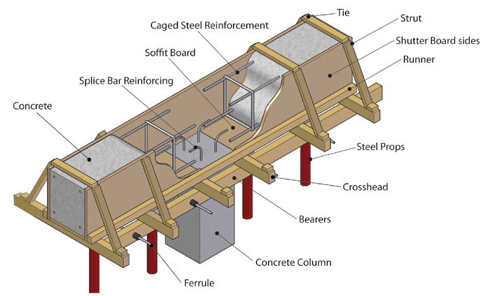
Figure 13.18 – Typical detail of beam formwork
Brickwork
Outline
Brickwork can be defined as a wall made up of courses of bricks or blocks laid in mortar according to a recognised bond to ensure the stability of the structure and when required to provide a finish that is aesthetically pleasing. Brickwork is strong and durable provided it is built properly. This entails the correct choice of mortar, masonry units, suitable damp proof courses, reinforcing, movement joints, pointing and includes of course skilled bricklaying.
Damp proof courses
Damp proof courses (DPC) need to be installed to prevent moisture and water seepage through walls etc. DPC is a sheeting of impervious material; Mastic asphalt, bitumen polymer and fibre felt or embossed polyethylene pre-manufactured in rolls, to suit the different widths of brickwork, also available in different thicknesses known as microns (μm) with the most common being 375 μm.
The three basic methods of protection in which DPC courses are used, are:
- To prevent moisture penetration from below (rising damp)
- . To prevent moisture penetration from above
- To prevent moisture penetration from the side (horizontal entry)
Typical applications
DPC at ground level is to prevent rising damp; it is laid at surface bed level, (see figure 10.19 – DPC to external wall) and depending on the masonry unit being used and finish, it should protrude the brickwork accordingly (see figure 10.21 – Typical examples of DPC installed in a double brick wall).
DPC in cavity walls is to prevent the entry of driving rain, the outer edge of the DPC is two brick courses lower than the inner edge and both edges are built into the bed joints. It is also installed to prevent rising damp. (See figure 10.20 – cavity wall construction)
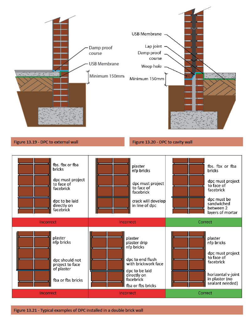
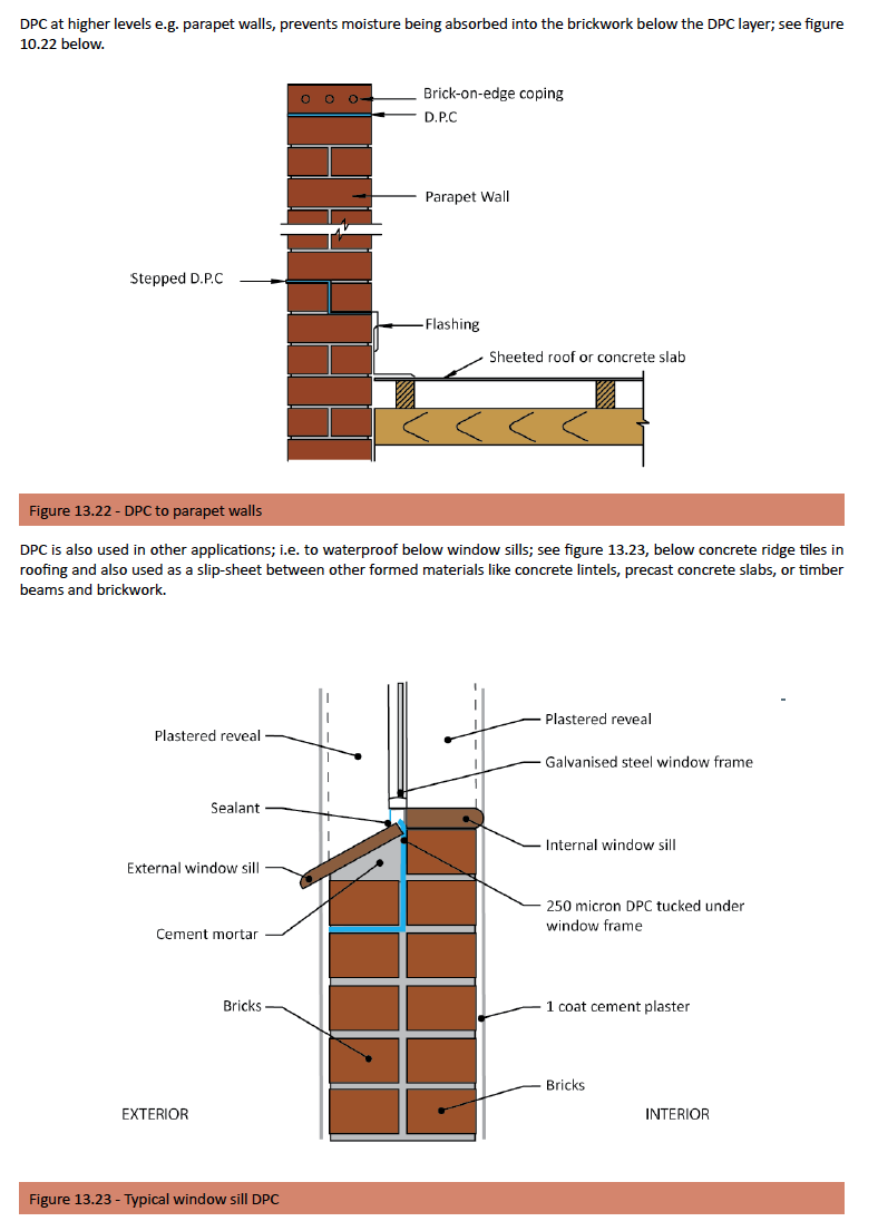
Standards
Extracts from SANS 10400: Part K
Any wall or sleeper pier of a building shall be provided with damp proofing and vapour barrier installations in such positions and to an extent that will reliably protect the wall against rising damp and
the interior of the building against ingress of moisture from abutting ground. Any material used as a damp-proof course shall comply with the relevant requirements contained in SANS 248, SANS 298, or SANS 952, or be the subject of an Agrément certificate. In a masonry wall, a damp-proof course shall be installed:
- a) at the level of the top of a concrete floor slab resting \ on the ground; or
- b) Where applicable, below any ground floor timber beam or joist.
In the case of any masonry cavity wall
- a) each leaf of such wall shall be provided with its own damp-proof course which shall extend over the full thickness of such leaf, in which case the cavity shall extend 150 mm below the damp-proof course; or
- b) each leaf of such wall shall be covered by a membrane which extends across the cavity provided that the position of the membrane at the inner leaf is higher than its position at the outer leaf; and
- c) Where necessary, weep-holes to prevent build-up of water in the cavity shall be provided in the external leaf of every cavity wall, spaced not more than 1 m apart, in the masonry unit course immediately below the damp-proof course contemplated in (a) or in the masonry unit course immediately above the membrane contemplated in (b)
Note: A damp-proof course should not be installed in any freestanding wall. Where moisture is likely to be encountered from ground water, high-density masonry units with a water absorption not exceeding 7% should be used up to 150 mm above ground level in order to prevent rising damp.
Bonds
The reasons for different bonds are firstly structural; bonding is required to strengthen and stabilize and form a monolithic wall, which will enable it to carry vertical and horizontal loads, for example English bond. Then economics (the most cost effective method of laying) and the wastage attributed to different bonds used, especially in blocks.
Finally, aesthetics needs to be considered, especially with face bricks. To maintain strength the bricks must overlap one another in the course above and below, not only on the face side, but also throughout the wall; see figure 13.24.
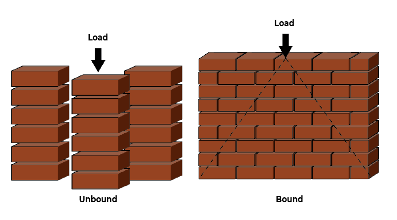
Figure 13.24 – Unbound and bound loads
Note: When Broken Bonding occurs where the length of a brick wall is not equal to brick format sizes, which means that a cut brick must be inserted. The cut brick should not be less than a half brick.
There are two known practical bond methods, that is, the quarter brick lap called the quarter bond, or the half brick lap called the half bond.If the lap is smaller or bigger, both the appearance and the strength of the bond are affected. The term used when no laps occur is the straight joint, which should be avoided in structural walls.
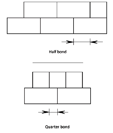
Different bonds
Stretcher bond
This is one of the few bonds, which can be used for half brick walling (single brick). On the face of the wall we see only the long stretcher face of the brick, except at corners, stopped ends and at cross walls. To ensure maximum strength the half bond must be maintained. At the junction of two walls a quarter bond is necessary but by inserting a three-quarter, the half bond is continued.
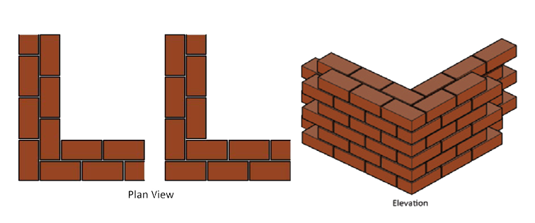
Figure 13.26 – Stretcher bond
English bond
This consists of alternate courses of headers and stretchers. Because we use a header course this bond is only suitable for walls from one full masonry unit and more i.e. a format of length to width of 2:1. This is a very strong bond because no straight joints appear. It is therefore ideally suited for walls where strength is important like retaining walls.
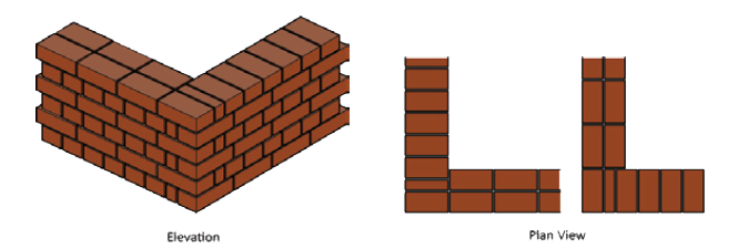
Figure 13.27 – English bond
Flemish bond
This method consists of alternate headers and stretchers in the same course. This bond is also reasonably strong because of the header bricks, which tie the two half brick stretcher skins together. This bond is usually used for aesthetics. In order to maintain the bond and avoid straight joints, the header brick in each course must be positioned exactly in the centre of the stretcher brick.
In practice, to maintain proper bonding, the cutting of masonry units to avoid straight joints is unavoidable; however, if the building is designed to standard masonry modules and correctly set out, the cutting of masonry units can be kept to a minimum. See figures 10.30 and 10.31.
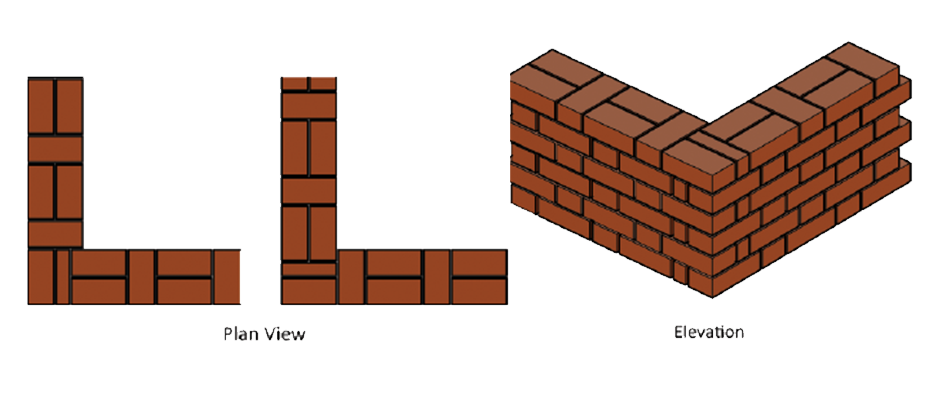
Figure 13.28 – Flemish bond
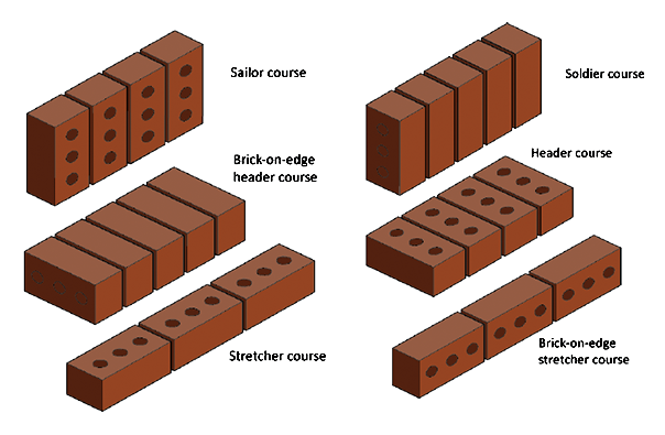
Figure 13.29 – different ways in which bricks can be laid
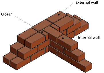
Figure 13.30 – Internal wall T- Junction with closers
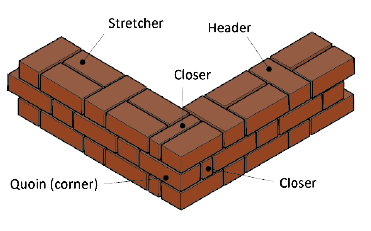
Figure 13.31 – Corner Flemish bond junction with quoin closers
Toothing and racking back
Toothing
A full or half brick is removed or a half brick projects from alternative courses of a wall in order to provide adequate bond if the wall is to be joined or connected at a later stage – see figure below. (Toothing is not usually permitted by many local authorities)
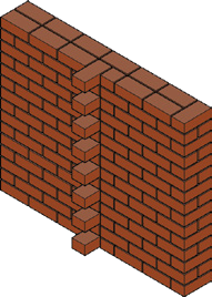
Figure 13.32 – Toothing
Raking back
The stepped arrangement formed during the construction of a wall when one portion is built to a greater height than an adjoining wall. It is recommended that no part of a wall during its construction should rise more than 900mm above another wall at one lift, if unequal settlement is to be avoided – see figure 13.33.
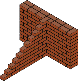
Figure 13.33 – Raking back
Jointing and Pointing
The reasons for jointing and pointing are firstly to prevent the penetration of water into the walls and secondly to provide a neat aesthetically pleasing finish, especially when using face bricks. Various tools are used to produce a smooth outer edge to the joints in order to allow water to run off without obstruction and thus prevent it from soaking into the brickwork by means of capillary actio.
Jointing is the process of finishing the face of the joint as the work proceeds. The actual mortar (Dagha) in which the bricks are laid is smoothed by means of the brick trowel or jointing tool; typically done when using stock bricks. Pointing is the process of raking out the joints as the work proceeds and at a later stage, filling and finishing them with specially prepared mortar; typically done on fair-face or face brickwork.
Raked out joints are done with the point of a trowel, a piece of hoop-iron or a nail head projecting from a piece of wood. In some cases raked out joints are left as is – but this is not recommended externally.
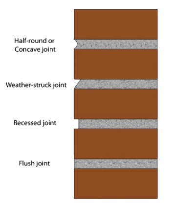
Figure 13.34 – Types of mortar joints
Cavity walls
Cavity wall construction should be used in coastal areas, or where exposure conditions are severe, and in high rainfall regions where the external walls do not have a chance to dry out properly. Keeping in mind that single-leaf walls are more vulnerable to moisture penetration than cavity walls in these circumstances.
A cavity wall basically comprises two single brick walls (skins – as it is also known) separated by a cavity of approximately 50mm, where the air space provides an excellent barrier against the passage of moisture. The two skins are tied together using wall ties
. It is very common to find that bricklaying mortar falls into the cavity and collects on wall ties, cavity trays and at the base of the cavity during the building process; resulting in potential bridging of cavities, leading to penetrating damp.
The removal of such mortar droppings from the cavity is critical and can be removed by providing temporary openings at the bottom of the cavity, which can be closed after the bricklaying process is complete and can also be used to form the weepholes.
Narrow cavity widths (less than 50 mm) increase the risk of rain penetration, as do wall ties, which slope downwards towards the inner leaf of the wall, recessed pointing, and inadequate projection of sills, copings, verges or eaves.
NB: Workmanship is particularly important in the construction of the outer skin of a cavity wall, so as to reduce the quantity of water passing into the cavity, and in keeping the cavity clear of obstructions and other faults, which can lead water across. If cavity insulation is to be used, good workmanship is also important for the installation of the insulation, either during construction (for built-in board or batt materials) or after construction (for blown-in or injected fills) – See installing thermal insulation later in this section
Note: In certain areas of the country, the cavity has been replaced effectively by a bitumen layer painted on the outside face of the inner leaf of a double skin wall.
Weepholes
Weepholes should be provided in the external leaf (skin) to prevent the build-up of water or moisture and are usually located in the first course above any damp-proof course membrane, and spaced approximately 900mm apart; and are typically formed as enlarged perpend joints of approximately 20mm wide. In hollow masonry unit walls, the weepholes should be of the same thickness as the bedding course thickness, of approximately 30mm wide and located in the bedding course beneath the hollow masonry unit cores.
Wall ties
Wall ties in cavity walls should be able to accommodate the movement between inner and outer skins. Butterfly, double triangular and modified PWD wire ties are more flexible and thus are preferred to flat or vertical twisted ties – see examples of wall ties in the following figure. Wall ties should be placed in the horizontal joints at intervals of not more than 600 mm in the horizontal direction and not more than 450mm in the vertical direction, except that within 150mm of the sides of any opening, this distance should be decreased to not more than 300mm. Ties should be staggered in alternate courses and be set level or with a slight slope to the outside leaf.
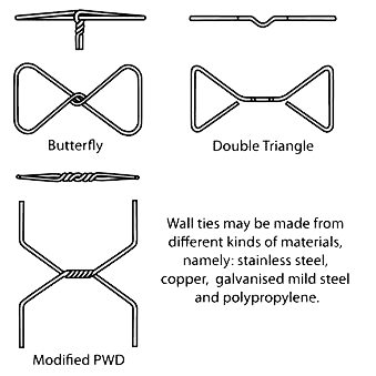
There must be at least 2.5 ties per m2 Metal wall ties shall either comply with the requirements of SANS 28, or
- a) be of galvanized mild steel wire with a minimum thickness of galvanizing of not less than 450 g/m2, or
- b) be of austenitic stainless steel and have the dimensions contained in the standard depending upon the tie type, and
Where required in terms of the specification data, and severe exposure zones metal wall ties shall have a minimum thickness of galvanizing of 750 g/m2 or be manufactured from austenitic stainless steel.
Thermal insulation
Polystyrene boards are the more common choice of cavity wall insulation; cavity fill (loose fill or injected foams) can be used; however, various issues associated with the use of cavity fill insulation have to be considered. Cavity fill is mainly used to insulate existing cavity brick walls. Check that local building regulations allow for the use of cavity fill or ask the manufacturer for a certificate of approval. Cavity fill must be treated to be water repellent. The reduction of heat flow inwards when a cavity wall is insulated using a 30mm polystyrene board compared to uninsulated cavity wall is as high a 64%.
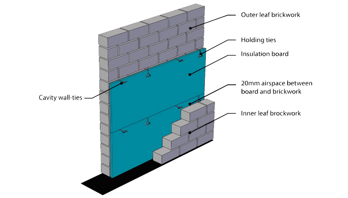
Figure 13.35 – Typical 3D section of cavity wall insulation
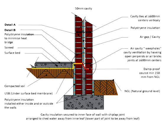
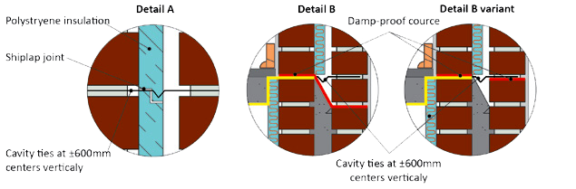
Figure 13.36 – Typical cavity wall insulation (please see details A and B)
Typical installation requirements
- Brick or block gauges are to be set such that cavity ties occur at 600mm vertical centres to coincide with the
horizontal joints of the wall insulation. - Cavity ties must be embedded to a depth of at least 50mm in the mortar joints of each leaf and spaced in the cavity as described above in accordance with SABS 0164, with holding back ties in between, to be embedded as per building standards (see detail A & B figure 13.35, 13,36).
- Boards must be secured against the inner leaf of the wall with the shiplap arranged to shed water away from the inner leaf, or with tongue facing upwards and secured with the holding back ties (see fig 13.3)
- Board support ties to be 2mm galvanised wire with fishtail ends.
- Boards must be tightly interlocked with no gaps occurring at the top and bottom of the wall, at corners and around windows and other openings.
- A run of boards may commence below a damp-proof course level to provide some edge insulation for the floor.
- Polystyrene insulation boards can be placed in a potentially damp position without losing thermal performance in the long term.
- Construct the outer leaf taking care to keep the residual cavity clean and secure the cavity ties. Please note that the construction of a cavity wall with insulation requires competent supervision, to ensure that the cavity is cleaned and the cavity ties properly secured.
- Polystyrene insulation boards are readily trimmed on site using a sharp blade or hacksaw to neatly notch board edges around wall ties and fit snugly around window and door-frames.
Brick reinforcement
Definitions
Reinforced Brickwork – Brickwork incorporating steel wire or rods to enhance its resistance to loads Reinforcing – Metal that is built into brickwork, e.g. reinforcing bars, brickforce.
Brickforce
Brickforce is used to reinforce brickwork especially in foundation brickwork and above the lintels of openings to windows and doors, and should provide a continuous band, particularly in the case of walls less than 190 mm thick, to form a lintel or “ring” beam. It is laid horizontally in the bed joints (the mortar joints) between brick courses and can be placed in every course above lintel height if specified or normally in every third to fourth course or at vertical centres that do not exceed 400mm. Brickforce is a light welded steel fabric made of two hard-drawn wires of diameter not less than 2.8mm and not greater than 3.55mm held apart by either perpendicular (ladder type) or diagonal (truss type) cross wires; perpendicular being the most common.
Where required in terms of the specification data, brickforce should be manufactured from pre-galvanized wire, galvanized in accordance with the requirements of SANS 935 for a grade 2 coating or be made of stainless steel wire.
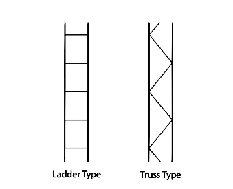
Brickforce is usually available in the following widths 75, 150, and 230 mm and in rolls of 20 metres.
Wire sizes available as recommended in mm are – 2,5 • 2,8 • 3,15 • 3,55.
The standard specification has a wire diameter of 2.00mm and the NHBRC specification is 2.80 – 2.50mm that is further covered by the National Building Regulations and the minimum requirements as specified in the NHBRC Home Builders Manual.
Rod reinforcement
Reinforcing steel including bed reinforcement shall comply with SANS 920 and SANS 1024. Reinforcement in a bed joint should comprise of hard-drawn pre-straightened deformed steel wire or rod wires that have a proof stress of 485 MPa and a
diameter of not less than 4,0mm and not greater than 6,0mm.
Mild steel has the disadvantage of being difficult to maintain in a straight position and because of its lower yield stress (250 MPa) it is required in larger quantities. At splices in the reinforcement the lap length of 280, 370, 460, 560, and 740mm are required for bar diameters of 6, 8, 10, 12, and 16 mm respectively.
Where required in terms of the specification data, rod reinforcement should be galvanized in accordance with the requirements of SANS 935 for a grade 2 coating or SANS 121, as appropriate or be made of stainless steel.
While bed joint reinforcement has been the traditional way of reinforcing walls, recent developments include the reinforcing of hollow blocks, both horizontally and vertically, or the filling with concrete of the cavities in cavity walls as a means to resist movement, to control cracking and to strengthen masonry.
Note: When galvanized brickforce or rod reinforcement is used, 0,10 g/L of potassium dichromate or 0,14 g/L of potassium chromate can be added to the mixing water for the mortar to ensure adequate bond to the reinforcement.
Lintels
Outline
A lintel can be best described as a small beam used over openings, windows, and doors, carrying the wall load only or a superimposed load like a roof. A lintel acts as a permanent shutter allowing bricklaying to continue almost unhindered. However, lintels on their own provide little compressive and tensile strength and only when combined with a number of brick courses, reinforcement and adequate bearing does a lintel then act as a beam, which can carry a load. Precast lintels must meet the following requirements:
- They must contain sufficient steel to carry the load once built in.
- They must be as light, and therefore slender, as possible.
- They must not crack easily when lifted or handled.
It has been found that the last two requirements can be met only if the concrete is pre-stressed, i.e. the concrete is “precompressed” so that it will not crack.
Prestressing is basically done, as follows:
Steel moulds, long enough to make several lintels end to end are placed side by side on a concrete bed. The ends of the moulds have holes in them; the hole diameter is slightly bigger than that of the prestressing wire. Movable stop-end plates, with holes in them, are placed in the moulds to divide the length into individual lintels. After the mould has been treated with release agent to prevent the concrete from sticking to it, the wires are threaded through these holes so that they protrude from each end of the mould. The wires are anchored at one end and connected to a powerful, usually hydraulic, jack at the other end. By activating the jack, the wires are stretched to the required extent and held in this state.
The concrete is then cast and when it has gained sufficient strength, the jack is released. The wires try to shorten to their original length but are prevented by the concrete, which grips each wire tightly. The effect of this on the concrete is to compress it, i.e. put it into a state of compression. We refer to this process as “prestressing.” Once prestressing has taken place, the wires between lintels are cut through. Lintels must comply with SANS 1504: Standard specification for prestressed concrete lintels. One must remember a lintel only forms part of the beam above an opening; the beam should comprise the lintel plus a number of brick courses with reinforcing between each course. Precast/prestressed concrete lintels are manufactured to suit various masonry units and are available in various sizes (see sizing table) Lintels should be laid with a minimum bearing on each side as follows:
- Lintel that supports masonry only – 150 mm
- Lintel that supports roof trusses
- Span less than or equal to 1,5 m – 150 mm
- Span between 1,5 m and 2,5 m – 250 mm
- Span greater than or equal to 2,5 m – 350 mm
Lintels should be temporarily supported in the centre for between 6 and 10 days depending upon the lintel length. The lintel should also be well watered during construction to ensure proper curing.
Note: A number of lintels are being installed in buildings today that do not match the application for which they are intended – a practice that is widespread and has serious consequences.
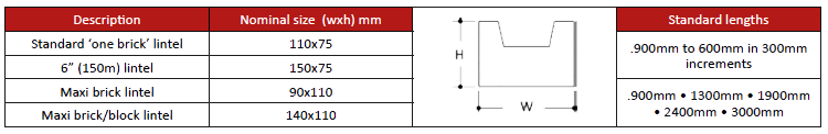
Standards
Guidance on the design of lintels over openings is given in appendix G of the Joint Structural Division of the South African Institution of Civil Engineering and the Institution of Structural Engineers’ Code of practice for foundations and superstructures for single-storey residential buildings of masonry construction. However, The National Building Regulations SANS 10400: Part K provides comprehensive guidelines for the installation of lintels, supporting tiled and sheeted roofs. Lintels which support concrete floors and roofs and timber floors fall outside the scope of this part of SANS 10400 and as such should be designed in accordance with the provisions of SANS 10400-B.
Extracts from SANS 10400: Part K
Bed joint reinforced lintels
Bed joint reinforced lintels shall have primary reinforcement located in the lowermost bed joints in accordance with tables 13.17, 13.18, or 13.19 and secondary bed joint reinforcement in the uppermost bed joint in accordance with table 13.20 and in accordance with the details shown in figure 13.37 – [SANS 10400:K – Figure 27].
Note: Tables 13.17, 13.18, or 13.19 provide reinforcing details for lintels supporting tiled and sheeted roofs.
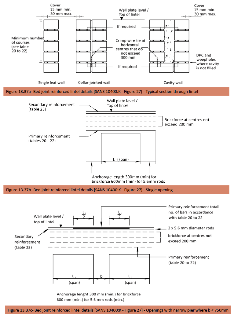
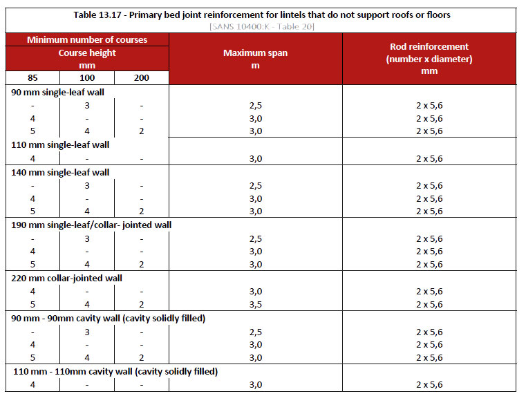
Note 1: If the cavity wall construction is not filled with infill concrete, the two leaves should be considered as independent leaves and be treated as single-lead walls.
Note 2: bed joint reinforced lintel details are shown in figure 13.37-[SANS 10400:K Figure 27]
Note 3: Table and figure numbers referred to in the figures are the SANS 10400 part K figure and table numbers as referred to in brackets after each table and figure.
Note 1: If the cavity in cavity wall construction is not filled with infill concrete, the two leaves should be regarded as being independent leaves and be treated as single-leaf walls. Reinforcement for the leaf, that is supporting the roofs, is determined in accordance with this table; reinforcement for the leaf, that does not support any roof, is determined in accordance with table 13.17.
Note 2: Heavy roofs are roofs with the following finishes:
- concrete roof tiles;
- clay roof tiles;
- slates; or
- thatch
Note 3: Bed joint reinforced lintel details are shown in figure 13.37 – [SANS 10400:K – Figure 27].
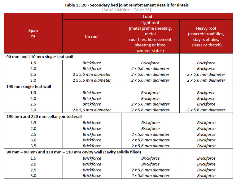
Note 1: If the cavity in a cavity wall construction is not filled with infill concrete, the two leaves should be considered as
independent leaves and be treated as single-leaf walls.Note 2: Bed joint reinforced lintel details are shown in figure 13.37 – [SANS 10400:K – Figure 27].
Masonry units in the lowermost course (course below the bed joint containing the reinforcement) shall either rest on the window or door frame below or, where practicable, be tied to the course above by means of crimp wire ties placed in cores or cavities or collar joints or perpend joints at centres that do not exceed 300 mm.
Precast concrete Iintels or lintel (U) blocks shall be used to form the bottom course in lintels where the soffit does not rest on a frame and the units cannot be tied to the course above by means of crimp wire ties. Brickforce shall be provided at centres that do not exceed 200 mm between the primary and secondary reinforcement described below.
Primary reinforcement as described below shall be located in the uppermost bed joint in accordance with the details shown in figure 13.38 where the pier between successive openings is less than 750 mm in width. The cores and perpend joints in hollow units shall be solidly filled with mortar or grade 10 concrete, as appropriate. Lapping of rod reinforcement shall not be permitted. The lap length in respect of brickforce shall not be less than 300 mm. Lintels shall be adequately supported for a period of not less than 7 days after completion.
Bond-block lintels
Lintels constructed by means of bond and lintel (U) blocks shall have primary reinforcement located in the block in the bottom course in accordance with tables 13.21 to 13.23, as relevant, and in accordance with the details shown in figures 13.38 and 13.39.
Note: Tables 13.21 to 13.23 provide reinforcing details for lintels supporting tiled and sheeted roofs. Lintels which support concrete floors and roofs and timber floors fall outside of the scope of this part of SANS 10400 and should be in accordance with the requirements of SANS 10400-B.
Lintels shall have the following secondary reinforcement provided in the uppermost bed joint:
- Spans up to 1,5 m – brickforce.
- Spans greater than 1,5 m – truss-type reinforcement having main wires not less than 3,55 mm in diameter.
- Alternatively, a bond or lintel block reinforced with a single Y8 bar may be used in lieu of brickforce in the uppermost
bed joint.
The cores of hollow units immediately adjacent to openings shall be reinforced with a single Y10 bar that extends from floor level to the top of the lintel (see figure 13.39) and shall be solidly filled with grade 25 infill concrete. The cores and perpend joints of units shall be solidly filled with grade 25 infill concrete, as appropriate. Lintels shall be adequately supported for a period of not less than 7 days after completion.
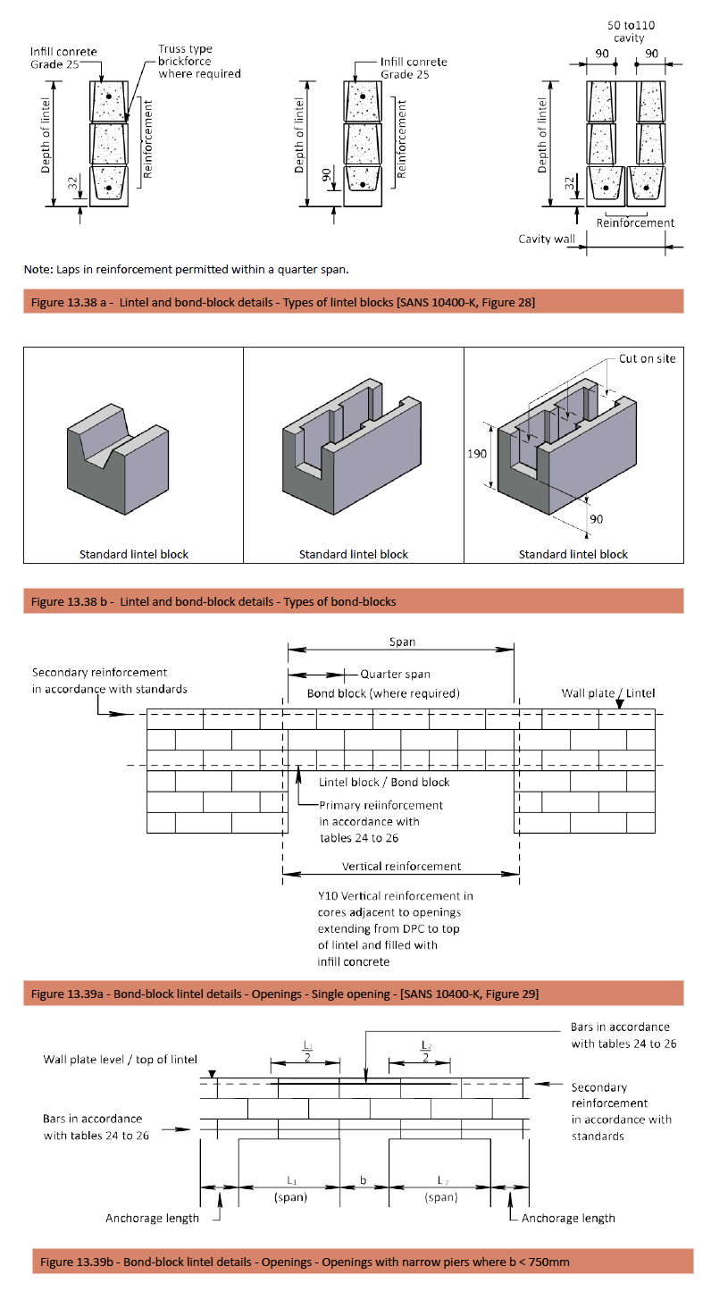
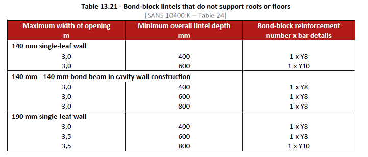
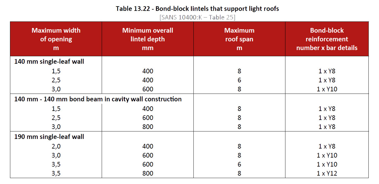
Note 1: The values given in respect of 140 mm single-leaf walls may be used where the cavity in the 140 mm – 140 mm bond beam in cavity construction is solidly filled with infill concrete.
Note 2: Truss-type reinforcement that has main wires not less than 3,55 mm diameter shall be provided in the uppermost bed joint if a bond-block beam does not form the uppermost course where the span exceeds 1,5 m.
Note 3: Light roofs are roofs with the following finishes:
- metal profile sheeting;
- metal roof tiles;
- fibre cement sheeting; or
- fibre cement slates.
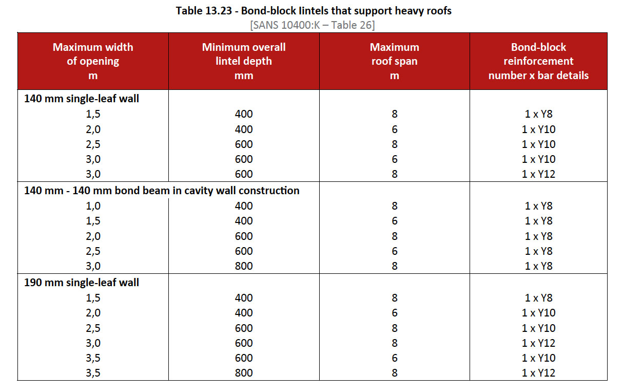
Note 1: The values given in respect of 140 mm single-leaf walls may be used where the cavity in the 140 mm
– 140 mm bond beam in cavity construction is solidly filled with infill concrete.Note 2: Truss-type reinforcement that has main wires not less than 3,55 mm in diameter shall be provided in the
uppermost bed joint if a bond-block beam does not form the uppermost course where the span exceeds 2,5 m.Note 3: Heavy roofs are roofs with the following finishes:
- concrete roof tiles;
- clay roof tiles;
- slates; or
- thatch.
Reinforcement may be lapped at the quarter spans; the length of such laps not being less than:
Y10 – 500 mm • Y12 – 660 mm • Y16 – 880 mm
Y10 – 500 mm • Y12 – 660 mm • Y16 – 880 mm
The side and top cover to reinforcement shall not be less than 30 mm.
Where the width of piers between adjacent openings is less than 750 mm, an additional bond beam shall be placed in the uppermost course that has the same reinforcement as would have been the case had it been a single opening. In such cases, the reinforcement in the bond beam immediately above the opening shall be not less than that given in tables 13.21 to 13.23, as appropriate. The upper bond-block beam shall be continuous across the pier and extend across at least one-half of the length of the openings on either side of the pier. (See figure 13.39.)
Precast prestressed concrete Iintels
Precast prestressed concrete lintels, which comply with the relevant requirements of SANS 1504, may be built into walls compositely with masonry in accordance with table 10.24 and figure 10.40 – [SANS 10400-K, Figure 30]
Note: Prestressed concrete lintels that do not comply with the requirements of SANS 1504, may be used as “non-structural” Iintels. Such lintels are regarded as being a series of masonry units, which merely replace the bottom course of masonry and shall be reinforced as described on the previous page.
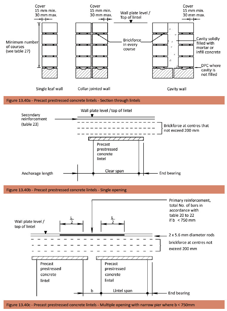
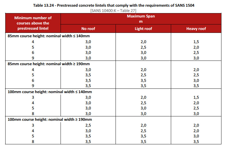
Note 1: Light roofs are roofs with the following finishes:
- metal profile sheeting;
- metal roof tiles;
- fibre cement sheeting; or
- fibre cement slates.
Note 2: Heavy roofs are roofs with the following finishes:
- concrete roof tiles;
- clay roof tiles;
- slates; or
- thatch.
Secondary reinforcement in accordance with table 13.20 shall be provided in the uppermost bed joint. Where the width of piers between openings is less than 750 mm, primary reinforcement in accordance with tables 13.17 to 10.19 as relevant, shall be provided in the uppermost bed joint, in accordance with the requirements of figure 13.37.
Lintels shall be set in mortar and have a minimum bearing of:
Lintel that supports masonry only: 150 mm
Lintel that supports roof trusses
- span less than or equal to 1,5 m: 150 mm
- span between 1,5 m and 2,5 m: 250 mm
- span greater than or equal to 2,5 m: 350 mm
Double garage openings
Lintels over double garage openings, which do not exceed 5,0 m, shall be reinforced in accordance with the provisions of figures 13.41 and 13.42 and table 13.24. Cores and cavities shall be filled with grade 25-infill concrete. Lintels shall be adequately supported for a period of not less than 7 days after completion.
Reinforcement may be lapped at the quarter spans; the length of such laps shall not be less than:
- Y10: 500 mm (min)
- Y12: 660 mm (min)
- Y16: 880 mm (min)
The side cover shall be not less than 30 mm.
The cores of any hollow units immediately adjacent to openings shall be reinforced with a single Y10 bar that extends from the floor level to the top of the lintel (see figure 13.39) and shall be solidly filled with grade 25 infill concrete.
Where the width of piers between adjacent openings is less than 750 mm, the primary reinforcement, as given in table 13.25 shall be provided at the top of the lintel and extend across at least half of the length of the openings on either side of the pier. (See figure 13.45.)
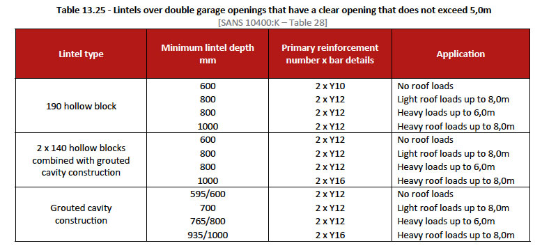
Note 1: Light roofs are roofs with the following finishes:
- metal profile sheeting;
- metal roof tiles;
- fibre cement sheeting; or
- fibre cement slates.
Note 2: Heavy roofs are roofs with the following finishes:
- concrete roof tiles;
- clay roof tiles;
- slates; or
- thatch.
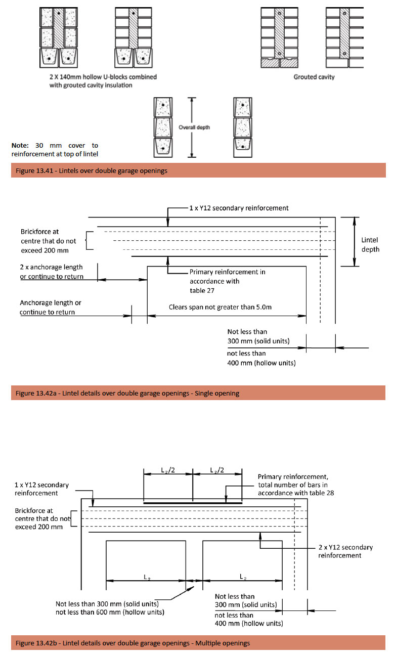
Roof anchoring (ties)
In the case of a wall erected of masonry units or of concrete, a galvanized steel strap (hoop iron) or wires must be embedded in the wall at positions suitable for anchoring any roof truss, rafter, or beam to such wall. Such strap or wires shall extend into the wall to a depth of at least 300mm in the case of a heavy roof (concrete or clay tiles or slate) or at least 600mm in the case of a light roof (a sheeted roof); except that in the case where the depth of the masonry or in-situ concrete is less than 300mm and 600mm, respectively, such strap or wire shall extend as far as possible into the masonry or concrete. Also, see Table 13.27 Minimum depth of anchor embedment under standards. Galvanized steel strap anchors shall be taken up over the top of the rafter or tie beam, or beam, bent down on the other side and nailed down from both sides; or galvanized roof wires/ties shall be made up of two strands of wire which shall be taken up on either side of the rafter or tie beam, or beam, twisted together so as to have no slack, but not so as to overstrain the wire, and the free ends then nailed down to prevent untwisting. See figures 13.43 and figure 13.44.
Standards
Timber roof trusses, rafters, and similar structures shall be fixed to walls by means of the following anchor types, selected in accordance with table 10.26 below:
- Type A: two strands of 2,4 mm diameter galvanized steel wire
- Type B: 30 mm x 1,2 mm galvanized steel strap
- Type C: 30 mm x 1,6 mm galvanized steel strap
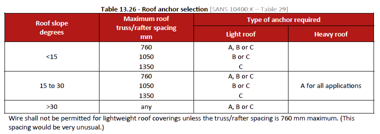
Note: Heavy roofs include those covered with concrete tiles, clay tiles, or natural slates. Light roofs refer to metal or fibre cement, profiled sheet roofs, fibre cement slates or metal roof tiles.
In the case of a wall of concrete or erected with masonry units, the galvanized steel strap, or wires shall be embedded in the wall at positions suitable for anchoring any timber roof truss, rafter, or beam to such wall. Such anchors, where practicable, shall extend to a depth shall be not less than that specified in table 13.27 below.
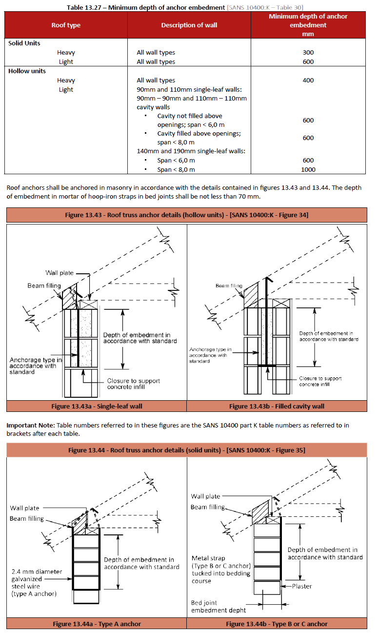
Window sills
A window sill can be best described as the horizontal ledge below a window. An external sill should be weathered outwards (have a fall) and should have a drip underneath to protect the top of the wall against rainwater and to prevent staining (water marks) from occurring on the wall below the sill. In brickwork walls, an external window sill can be of standard imperial bricks laid on edge or special bricks laid on edge, left exposed in the case of face bricks or plastered in the case of plaster (stock) bricks. See figure 13.45 – Typical window sill details on the next page.
Sills manufactured of various other materials like clay or ceramic tiles, precast concrete, fibre cement, and plastics or composites, can be used externally and internally and for obvious reasons timber sills can only be used internally.
An internal sill is usually installed in a horizontal level position and should be made of a material that can be installed easily and should be sealed with silicone at the side adjacent to the window frame and the reveals to provide a proper seal and to fill the joint between the different materials, as movement cracks will appear over time. One of the most important details with an internal sill is to ensure the gap between the bottom of the window frame and the last course of brickwork can accommodate the thickness of the material being used or specified and that this type of installation is required i.e. the sill fits under the frame.
Note: The Sealing of window and door frames including internal sills within the structure, with silicone or mastic, improves airtightness and energy efficiency.
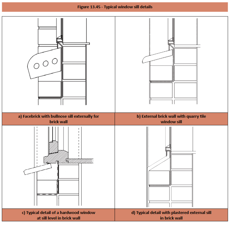
Brickwork Movement
Outline
All structures are subjected to varying degrees of dimensional change after construction. Determination of movement in response to the environment is a complex problem and not merely a summation or subtraction of extreme or individual values of thermal and moisture movement, but the response of the masonry to these movements must be considered. It is also, often found that the orientation will induce different movements in various parts of the walls due to the incidence of radiation heat or prevailing rain. That is why one must make allowance for movement joints (which some call expansion, control or soft joints), in the design of buildings. An estimation of potential movement in a masonry element must rely to a great extent on engineering judgment. Many factors, such as temperature and moisture content of masonry units and mortar at the time of construction, the exposure to weather conditions and degree of restraint imposed on elements subject to movement are unpredictable.
In general, it is more simple to adopt empirical rules rather than try to estimate movement in a structure from first principles. Stresses in masonry that are sufficient to cause cracks may be controlled to some extent or reduced by the use of control joints or reinforcement and by the degree of restraint inherent in the masonry and the supporting structure, namely the foundations, beams, slabs, etc. Not all movements are reversible. When the stimulus to movement is removed, for example when severe contractions cause cracks in perpend joints, or when the bond strength between the masonry unit and mortar is exceeded, the crack may not be able to close again due to mechanical interlocking, friction or insufficient force in the opposite direction. With repeated expansion and shrinkage movement, cracks can become filled with debris, resulting in a ratchet effect which results in a continuous increase in length of the masonry. Recommendations for the size and spacing of control joints to accommodate movement are given in SANS 10249 and joint spacing recommendations associated with quantities of reinforcement are given in SANS 10145. Guidelines of spacing between vertical control joint in walls is given in SANS 10400: Part K – see extracts from this standard in standards that follow.
In clay brick walls
Typically, movements can be as much as 5 mm in 7.5 m of wall. Provision is usually taken to be 1 mm per metre to cope with a combination of irreversible moisture expansion, and reversible thermal and moisture movements. The recommendations of SANS 10249 for unreinforced masonry are not concerned exclusively with temperature size changes.
However, the Standard recommends that vertical joints in unreinforced burnt clay brickwork should be positioned not more than 18 m apart to avoid cracking due to thermal contraction. See Table 13.26 – Maximum spacing between vertical control joint in walls – under standards.
Where wall lengths need to be subdivided, the joint spacing can be determined by working back from the ability of the chosen joint design to accommodate size changes. Closer spacing than 18 m is likely to be needed where comparatively little restraint is imposed on size changes – as in parapet walls, for example. The vertical joint nearest to a salient or re-entrant corner should be located not further from the corner than half the general joint spacing elsewhere.
Additional joints (or, alternatively, reinforcement) may be needed at points of stress concentration – for example at openings. Movement joints in clay brickwork are to accommodate expansion, so must be able to close by prescribed amounts using compressible packing and non-setting mastics.
In concrete brick and block walls
Joints are specified to accommodate contraction of the wall, and the joints must be wide enough to prevent failure of the mastic in tension. SANS 10400: Part K recommends that, as a general rule, vertical joints should be at intervals of not more than 8 m. SANS 10145 permits joint spacing up to 9m for unreinforced masonry (“subject to the length of wall between control joints not exceeding twice the height of the wall”) and up to 18,5 m where vertical spacing of horizontal reinforcement is 200mm or less. The standard also notes that the risk of cracking increases if the length of a panel exceeds twice its height. These recommendations apply in the main to half brick thick walls. Provided suitable precautions are taken, for thicker walls the distances between movement joints may be increased. At changes of section, similar considerations to those noted above for clay masonry units apply.
Note: The requirement for a movement (soft) joint in walling is often overlooked until construction of that part of the wall is complete. A chase is then cut and filled with sealant giving the misleading appearance that the specification have been met.
Design and construction
The primary object of control joints is to divide the wall into separate panels in such a way that stresses along its length produced by differential movement and changes in volume of masonry units are relieved.
The design and positioning of control joints should accommodate movements but should not impair the stability of the wall or any of its functions, i.e. impermeability, sound insulation and fire resistance. Vertical control joints should be butt joints and the gap between adjacent surfaces should not exceed 12 mm.
Vertical control joints in non-reinforced masonry should generally be positioned where concentration of or changes in stress may occur, such as at: openings; major changes in wall height; changes in wall thickness; control joints in foundations etc.; one or both sides of wall openings, near wall intersections and near return angles in L, T and U-shaped structures. Control joints can also be located between openings. See figure 13.46 below. Control joints should be built into the wall during construction and should run the full height of the masonry. Sawn joints are generally more expensive, require great care in cutting and are not normally as effective as built-in joints. It is not usual to continue the joints below the ground floor damp-proof course where changes in temperature and moisture content are minimal.
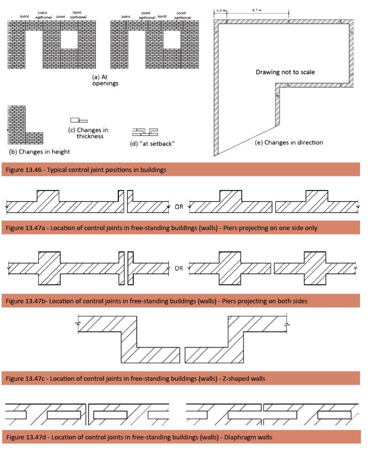
Note: All centre to centre dimensions of control joints must be in accordance with table 13.28
Standards
Extracts from SANS 10400: Part K
Extracts from SANS 10400: Part K
The overall length of a wall between free ends or returns shall not exceed the limits derived from table 13.28, unless vertical control joints have been incorporated into such wall so that the distance between a free end or a return and a vertical control joint, and the distance between vertical control joints is within such limits. A vertical control joint shall be provided where there is a storey height change in the height of the external walling and where setbacks produce a return on plan of less than 800 mm (see figure 13.46 above). Vertical control joints in free-standing walls shall be provided at the locations shown in figure 13.47 above and shall extend to the top of the foundation. Vertical control joints should be 10-12mm wide
Note: Control joints are not required to continue below ground floor level except at changes in level and in
free-standing walls.
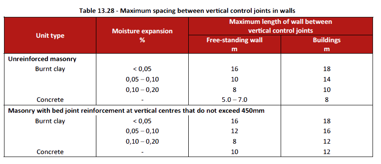
Note 1: SANS 227 contains a test procedure to establish the moisture expansion of burnt clay bricks
Note 2: In wall construction that comprises hollow masonry units, the placing of Y8 bar in bond beams at centres that do not exceed 1200 mm (generally in the course below slabs, below sills, above windows and above doors and in the uppermost course) may be regarded as being equivalent to bed joint reinforcement.
Arches
Arches are arrangements of well shaped bricks called ‘voussoirs’ which are designed to support each other and carry the load over the opening, round the curved profile, to abutments on either side. An exception to this form is the flat or ‘soldier’ arch, which is constructed of bricks laid on edge or on end.
Arches seldom require additional reinforcement because of the wedge-shape form of the units, and as a result of this, the more the load that is placed on an arch, the tighter the units in the arch will become. This is because the pressure is transmitted downwards.
Terminology
Voussoirs
The wedge-shaped bricks in an arch.
Key brick
The highest or central brick and usually the last to be built in.
Bed joints
The joints between voussoirs. Span – the horizontal distance between the jambs of the opening over which an arch is bridged.
Intrado
The underside edge of an arch when seen in elevation.
Soffit
The inner or underside of an arch.
Springing points
The lowest points of an arch from which the arch curve starts.
Springers
The bottom bricks (voussoirs) on either side of an arch.
Rise
The vertical distance between the springing line and the highest point of the soffit (intrados).
Crown
The highest point of the arch at which the key brick is placed.
Extrados
The upper edge of the arch as seen from the front.
Face
The outside surface of the arch between the extrados and intrados.
Ring
Row of bricks in the arch.
Haunch
The lower half of the arch between the crown and the springing line.
Skewback
The inclined or splayed surfaces of the abutments prepared to receive the arch and form which the arch springs.
Abutments
The portions of the wall which support the arch.
Depth or height
The normal distance between the intrados and the extrados.
Arcade
A series of arches, adjoining each other, supporting a wall and being supported by piers.
Template
The term given to a piece of material which is marked out from the full size drawing of an arch and cut to the shape of the arch voussoirs. The arch bricks (voussoirs) are then cut to match the shape of the template.
Striking point
The centre point from which the curve of the arch is drawn.
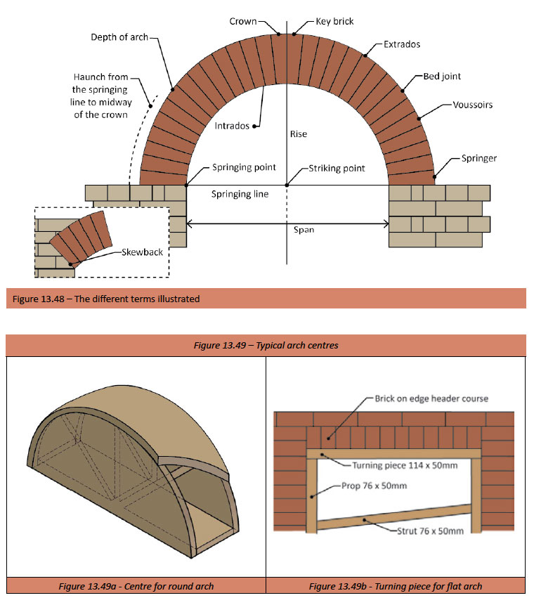
Arch centres
The arch centre is used for the same purpose as a turning piece in a flat arch; as a temporary support to carry the arch during its construction over an opening, and is made up of a number of timber members cut to the required shape. Centres may be open or closed. Closed centres are preferred because the voussoirs are marked out on the thin plywood or hardwood nailed to the ribs and sides of the centre. Furthermore a closed centre provides a smooth surface with which to work.
Note: If the span of the flat arch exceeds 1.5m it then becomes necessary to install a centre prop to prevent the turning piece from sagging.
Types of arches
Ringed or Rough Arches
This type of arch is the simplest to construct and is formed using ordinary un-cut bricks and, with bricks being rectangular in shape, they give rise to wedge shaped mortar joints. The shape of the arch is controlled by the type of turning piece or centre used to construct the arch. To prevent the thick end of the mortar joint being too big, rough arches are usually constructed of half brick or brick on edge courses. The ringed or rough arch is used where appearance is not important, and also sometimes used in face work where budgets don’t allow for gauged arches.
Gauged Arches
These are true arches and are constructed of bricks cut to the required wedge shape (voussoirs), using a template. The purpose of voussoirs is to produce a uniform thin joint which converges onto the centre point or points of the arch. Cutting the bricks to the required wedge shape is done using a diamond or carborundum blade saw.
Obtaining the template
Half the arch is set out to its full-size on a thin sheet of plywood or hardwood. When the setting out has been checked accurately, the voussoirs templates are carefully sawn out to the required shape. These are in turn used as individual templates for the arch bricks. Each template is used twice, first for the one side then for the other side.
Shapes and Setting out Arches
Flat Arch
The name of the arch indicates that it is intended to be perfectly horizontal, but to prevent the optical illusion of sagging, it is given a slight camber or rise. The amount of camber given to the arch soffit is usually 3mm per 1000mm of span.
To set out a flat arch
- Draw the springing line
- Parallel to and 225mm above it, draw the setting out line
- Erect a perpendicular at the springing line to intersect the setting out line, giving the centre of the flat arch; this enables the correct setting out of the header or soldier course placed on each side of the centre line.
- Before placing the bricks on the turning piece (the centre) remember to allow for the camber or rise, using wet plaster sand or a very weak mortar (when using mortar with face bricks, place a sheet of DPC as a slip sheet over the mortar before placing bricks)
- See figure 13.50
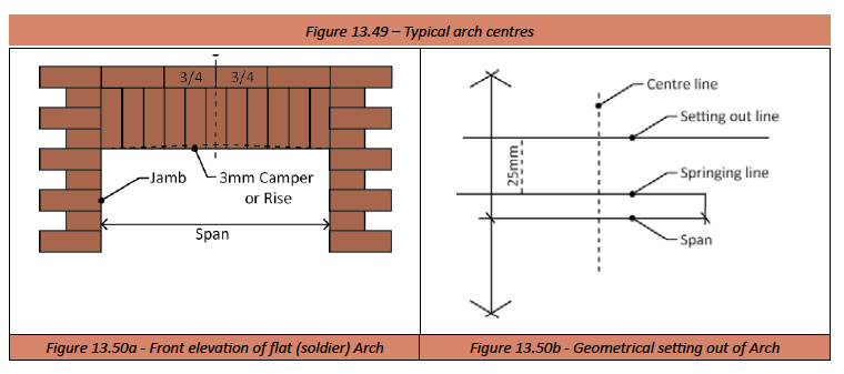
Semi-Circular Arch
The setting out of a semi-circular arch is simple. Half the span is the rise; see figure below.
The setting out of a semi-circular arch is simple. Half the span is the rise; see figure below.
To set out a semi-circular arch
- Draw the span
- Establish the radius
- Establish the springing line – the line of the 1st Brick (springer)
- Establish the striking point (centre of springing line)
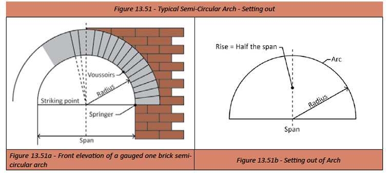
Segmental Arch
Rough segmental arches are arches built of standard bricks and the mortar between each brick is wedge-shaped. These
arches are normally built using stock bricks, as this kind of arch is usually used internally as a relieving arch.
Note: Before this kind of arch can be set out, the rise must be known; the rise is normally one-sixth of the span.
To set out a segmental arch
- Draw the span (for purposes of illustration assume it to be 900mm)
- Draw a perpendicular bisector (In the figure below the dotted line)
- Mark off rise (in this case 150mm)
- Join the span and perpendicular bisector, points (a) and (b) and bisect
- Where the bisector intersects the centre line (perpendicular bisector), is the striking point of the required arch. Point (c)
- See figure 13.52 illustrating the above
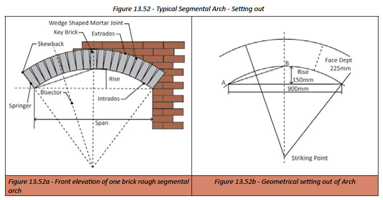
Points to remember when constructing arches
- The key brick is always in the centre of the arch
- In the case of double ring arches, each ring is treated as a separate arch
- When constructing a gauged or axed arch the voussoirs are marked on the extrados
- When constructing a rough arch the voussoirs are marked on the intrados
- In ringed arches the voussoirs are laid as a brick-on-edge- course
- When constructing the template used to cut the bricks to the required shape in an axed arch it is important to note that
the widest part of the template must not exceed 73mm (the height of the brick) - All the bed joints radiate to the centre or striking point
- Voussoirs of the same ring must be equal in size.
Standards
Extracts from SANS 10400: Part K
Masonry arches
Extracts from SANS 10400: Part K
Masonry arches
Circular masonry arches that have a span that does not exceed 2,5 m shall have an arch ring depth and proportions as shown in figure 13.53. Such arches shall be constructed as follows:
- a) The rise shall be between 0,3 and 0,5 times the span
- b) Masonry units shall be solid.
- c) The arch ring shall be constructed in either header or stretcher pattern.
- d) The arch ring depth shall be:
- not less than 200 mm where the rise is between half and two-thirds of the radius,
- not less than 300 mm where the rise is greater than two-thirds but less than or equal to the radius
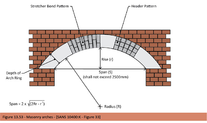
Columns
Columns discussed here are of the more decorative type albeit they can be used structurally and not the concrete columns found in reinforced concrete framed structures. The variation in width (diameter) and length of decorative columns is substantial and normally project specific, whereas the profiles are more generic and can be either round or square. Columns also come in various forms for example, tapered, fluted, reeded, plain or have a entasis.
Definitions and terminology
Pilaster
A pilaster is a rectangular pier, sometimes fluted, projecting from the face of the wall having a cap, shaft and a base. It also serves as a buttress to strengthen a wall. The term “attached pier” is a more common form for this type of pier.
Pier
A pier is the load-bearing brickwork between openings. The pier can be freestanding, or it can be attached to a wall where the term pilaster applies.
Columns
A column is an upright shaft generally rectangular or round, usually manufactured from concrete, pre-cast concrete, brick, fibre cement, or steel. Columns are often connected by a member known as an architrave, that forms the lower section of the entablature. The column typically comprises of three parts; the base, shaft and cap. Columns may be plain or fluted (vertical groves down the sides). Columns may also have a delicate swelling known as ‘Entasis’.
Entasis
This is the outward bulging swelling in the shaft of a column, and can be further defined as a slight convexity in the shaft of a column, which compensates for the illusion of concavity that viewers experience when the sides are perfectly straight. As a rule in the more graceful columns, the entasis is very slight.
Erecting free-standing columns
Pre-cast concrete columns
- The columns are to stand on properly prepared and designed concrete foundations. The design of the foundation should take into account the size and weight of the column itself, any anticipated external forces, and the nature of the soil conditions. Typically, a freestanding column foundation would have proportions of approx. 400 x 400 x 200 mm.
- Assuming adequate foundations have been prepared, the next step is to drill into the foundation and epoxy in one or more steel rods (diameter approx. 10 mm). These rods are to be positioned so that they correspond with the hole in the centre of the precast base, and should be as near to the sides of the hole so as not to clash with the reinforcing of the shaft. Alternatively, these rods could be positioned at the time of casting the foundation.
- The precast base (if being used) is then positioned over these rods and is bedded down using a strong mortar. Care is to be taken to ensure that the hole in the precast base is not filled. The bases are then left for at least 24 hours, before positioning the column shafts.
- Immediately prior to placing the shafts, the hole in the precast base is filled with a strong concrete mix. The shaft is then set down on the precast base with the reinforcing bars of the shaft extending into the newly placed concrete. The reinforcing bars of the shaft should be checked for length prior to this, and trimmed if necessary. The shaft is to be plumbed and supported using wedges and timber planks, and left alone until the next day.
- Finally the cap is placed on top of the shaft and the hole in the cap is filled with the same mix as was the base. At this point, whatever may be required for the next stage of construction, should be cast into the cap e.g. bolts, wire ties, brackets, reinforcing rods, hoop irons, etc.
- All that remains is for the entire column to be finished off, pointing the joint between base/shaft and shaft/cap, and filling the scratches that occur during handling.
- The strength of the column installation should not be tested until the concrete has had time to gain strength.
Hollow fibre cement building columns
- Building columns are to stand on properly prepared and designed concrete foundations. The design of the foundation should take into account the size and weight of the column including the concrete when filled and any anticipated external forces, and the nature of the soil conditions. Typically, a free-standing column foundation would have proportions of approx. 400 x 400 x 200 mm.
- Assuming adequate foundations have been prepared, the next step is to drill into the foundation and epoxy in one or more steel rods (diameter approx. 10 mm). These rods are to be positioned so that they correspond with the inside diameter of the hollow building column, and should not to clash with the reinforcing of the building column where required. Alternatively, these rods could be positioned at the time of casting the foundation.
- Determine whether any cut-outs in the column are required for services, water outlets, bolts etc. and cut out before the column is placed in position.
Note: Where building columns are designed as load bearing elements in buildings, they should be considered as permanent shuttering only and the reinforced concrete core requires professional expertise and should be designed by a professional engineer.
- When setting up the column on a concrete foundation, the column must be kept in position by framing the base of the column with a timber frame which is nailed down to the concrete. A similar timber frame to which the stays for bracing can be attached should be fixed to the top end of the column; or by using a precast concrete base, which will be kept in place permanently, installed as per pre-cast concrete columns above.
- Ensure that the reinforcing steel is properly positioned, before the next step commences.
- While pouring the concrete check the bracing and ensure that the column is in a plumb position and that the reinforcing remains correctly positioned. Concrete in longer columns should be done incrementally to avoid the building column from bursting open at the base. Do not tap sides of column with a hammer to distribute the concrete, use a concrete vibrator.
- Do not lean ladders against the column for pouring of concrete, use scaffolding platforms
- Clean off excess concrete which may have splash onto the column before it hardens.
- Finally if a cap is being used, it is placed on top of the column and the hole in the cap is filled with the same mix as was the column. At this point, whatever may be required for the next stage of construction, should be cast into the cap e.g. lintels, wire ties, brackets, reinforcing rods, hoop irons, etc.
- Bracing can be removed after a minimum of 48 hours.
Bases
Moulded bases are normally used for decorative purposes and to facilitate setting out and are usually manufactured from pre-cast concrete; see example below.
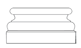
Caps
Caps serve a dual function depending whether the column or pier is isolated or not. They are usually manufactured from pre-cast concrete and used for decorative purposes. Where the columns or piers are built in, the cap fits over the shaft of the column and whatever may be required for the next stage of construction, should be cast into the cap; see example overleaf. Where columns or piers are attached or isolated, the precast concrete cap is installed to provide cover to prevent moisture from penetrating the top of the column or pier; see example below Where caps are used to provide cover it is advisable where possible, to provide a generous overhang to allow water to fall clear from the column, a good fall and a minimum number of mortar joints if bricks are being used.
When fixing pre-cast concrete caps, it is recommended that a stronger mortar mix be used and the cap is kept moist to allow for proper curing. And in the case of brick on edge caps a DPC layer should be used directly below the course of brickwork immediately below the brick cap level. A gauge rod should always be used to set out the brick on edge caps and copings, to avoid any unnecessary cutting, and to determine accurate minimum joint sizes.
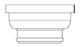
Freestanding walls
Outline
Freestanding walls can be defined as walls not forming part of the building, and are generally used for boundary demarcation, landscaping, screening, security, and noise barriers. By their nature they are exposed to the elements and to wind loadings on both faces and need to be designed to ensure that local wind loadings are taken into consideration. Most freestanding walls are constructed using bricks or blocks and can be finished in either face-brick, semi face, fair face or plastered and painted. Depending upon the height, freestanding walls are usually subject to plan approval by the local authority/municipality.
Walls are normally formed in brickwork, and usually will be reinforced when over 2500mm in height. In sheltered areas, where wind speeds are low, they may be unreinforced up to 3000mm in height, while in areas with high wind speeds lower heights may require reinforcement. As a general rule, walls exceeding a height of 2500mm require that the wall be designed by a structural engineer or other suitably qualified professional.
The minimum requirements of wall thickness and heights are given in the tables below, under standards – Extracts from SANS 10400 Part K. The wall height is measured from the lowest ground level to the top of the wall, capping or coping. For ground slopes of between 1 in 10 and 1 in 20 wall heights should be reduced by 15%. Formal design procedures should be adopted for sites with steeper slopes. Diaphragm wall construction can be used as an alternative to using reinforcement, but is unlikely to be economical. Piers will be needed where gates are to be hung, the design depending on the circumstances.
Foundations
For walls not exceeding 2500mm in height a foundation depth of 500mm is normally adequate in good ground. For higher walls in solid soils the foundation depth should be 750mm minimum. Generally, it should be possible to found a freestanding wall at half the depth recommended for residential buildings (See Foundations). However, where walls are to be founded on highly shrinkable soils (clay) or close to large trees (or where large trees have been removed) foundation depths and details should be based on the recommendations of a structural engineer or that of a suitably qualified professional.
Foundation width is normally calculated by the following rule of thumb; the wall width plus 300mm and shall not be less than 150mm thick. Wherever possible, avoid construction on made ground unless properly compacted. It is also important to remember a number of local authorities/municipalities will not allow the concrete strip footings of a boundary wall to encroach over the boundary line. Should this be the case either a bootleg footing can be used or the actual boundary wall would need to be set back by the width of the exposed side of the footing.
Standards
Extracts from SANS 10400: Part K
Free-standing boundary and garden walls shall be designed and constructed so that:
- a) the height of the wall (see figure 13.54-f) does not exceed the values given in tables 13.29 and 13.30, provided however, that where x (see figure 13.54- f) exceeds 0,3 m, the height is reduced by the difference between x and 0,3 m,
- b) no earth is retained,
- c) piers extend to the top of the wall without any reduction in size,
- d) walls terminate in a pier or a return, and e) the cores of all piers are solidly filled with mortar or infill concrete where units are hollow.
- No horizontal damp-proof course (DPC) shall be provided in free-standing walls.
- Where moisture is likely to be encountered from ground water, high density bricks with a water absorption not exceeding 7% shall be used up to 150 mm above ground level in any free-standing wall.
- Where any wall consists of sections of two or more different thicknesses, the maximum height of any such section shall not be greater than the value given in Table 13.29 or 13.30 for the thickness in question. The sum of the heights of the various sections of such a wall shall not be greater than the value of the maximum height given in Table 13.29 or 13.30 for the thickest section of such a wall.
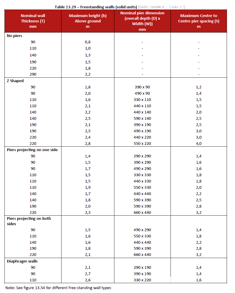
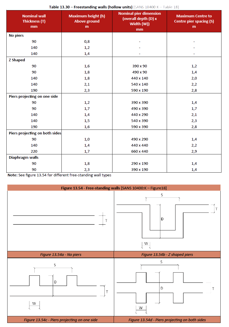
Balustrade and parapet walls
Balustrade and parapet walls shall not be less than 1,0 m inheight unless unauthorized access of persons to the edge of a flat roof or similar structure is excluded by a physical barrier properly erected and monitored. Free-standing balustrade and parapet walls shall have a thickness of not less than the height of the wall above the base divided by:
- a) Solid units:
- no DPC at base: 5,0
- DPC at base: 4,5.
- b) Hollow units that have cores filled with infill concrete:
- no DPC at base: 4,0
- DPC at base: 4,0.
Balustrades and parapet walls that have returns which continue for a distance of at least 0,75m from the external face of such walls or are fixed to columns at centres that do not exceed 3,5 m, shall have a thickness of not less than:
- solid units 110 mm
- hollow units 140 mm
Copings
A coping is a cover fitted to the tops of freestanding (boundary), parapet and balustrade walls, and to brick piers, also referred to as caps. The primary function of a coping is to prevent moisture from penetrating the tops of walls and also helps reduce streaks being visible on the wall below, because they are usually weathered away at a slope and have drips. Copings advance the long term durability and stability of walls and also provide an aesthetically pleasing finish to walls.
There are typically four types of copings used today; Brick, precast-concrete, composites and stone. For copings to be effective they should have the following qualities:
- Be impervious to any water entering the top
- Contain a minimum amount of mortar joints
- Have a fall on its surface
- Have sufficient overhang to allow water to fall clear from the wall
- Have a drip
Corbelling
Where courses are corbelled out one above the other, the extent of corbelling shall not exceed that shown in figure 13.56 .
Scaffolding
Scaffolding is a temporary platform carried by a framework erected on site, to give access for trades like (bricklaying, plastering, and painting) and to carry materials. It is usually a modular frame system of metal or aluminium, although it could be made out of other materials.
Scaffold staging or tower scaffolds are usually of steel or aluminium, either of a prefabricated frame type that clip together or of a tubular type joined with fittings, for example a putlog coupler.
Scaffold boards or planks which form the working deck or platform of a scaffold, must be strong enough to carry the materials and workers. They are either wooden planks and should be at least 228mm wide and 50mm thick and not be longer than approximately 4,8m with a maximum support distance of 2,2m; or steel planks which clip into the framework and are typically 228mm wide.
Scaffolds are rarely independent structures. To ensure a constant and workable space between the structure and the scaffold, ties are used to link the two, which also ensures the scaffold remains sturdy.
- Scaffolding can be categorised in the following forms
- Steel builders trestles
- Scaffold frames
- Independent (purposely erected) scaffolding
- Mobile scaffolding
Steel builders trestles
A standard steel builders trestle can be used for almost every type of interior and external building activity up to about 2,4m (single storey buildings). It usually accommodates a four board working platform of approx. 1,0m wide, and is easily handled by one person and folds away for quick storage and transport.
Trestles are usually available in the following heights:
- 800 – 1000mm extending to approx. 1.800mm (Ideal for fitting, plastering and painting ceilings)
- 1200 – 1400mm extending to approx. 2.000 – 2400mm (Ideal for brickwork and plastering)
Scaffold frames
These frames are very popular due to the speed of erection and are easy to transport and when dismantled they can be stored with ease. Scaffold frames or as some refer to as speed frames do have the disadvantage of becoming dangerous if heights of 6.0m are exceeded. A further drawback in using this type of scaffolding is if used in long lengths of wall, many frames need to be erected to provide adequate support for the platforms. Scaffold frames are suited to more short duration tasks for example painting or for the fitting of fixtures.
Independent scaffolding
Independent scaffolding can be best described as a scaffold with at least two rows of standards and is independent of wall support except for stability ties. The key elements of an independent scaffold are standards, ledgers, and transoms. The standards, also called uprights, are the vertical pipes that transfer the entire mass of the structure to the ground where they should rest on a square base plate to spread the load. The base plate has a shank in its centre to hold the pipe and is sometimes pinned to a sole board, to prevent kicking.
Ledgers are horizontal pipes which connect between the standards. Transoms rest upon the ledgers at right angles. Main transoms are placed next to the standards; they hold the standards in place and provide support for the platform.
See Figure 13.57 – Vertical section of typical scaffold.
As well as the pipes at right angles there are cross braces to increase rigidity, these are placed diagonally from ledger to ledger, next to the standards to which they are fitted. If the braces are fitted to the ledgers they are called ledger braces. Longitudinal bracing can be fitted diagonally across the front of the scaffold from corner to corner or in a zigzag pattern, from standard to standard.
See Figure 13.58 – Independent tied scaffolding.
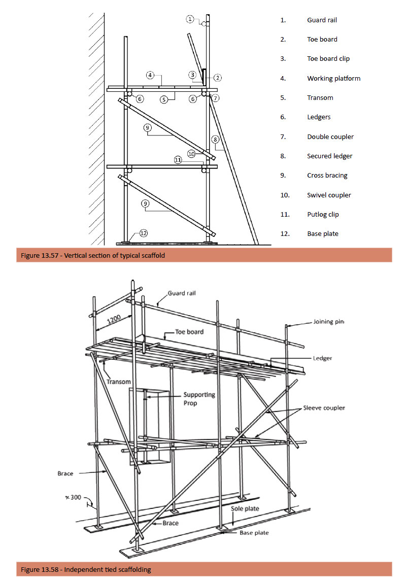
Independent scaffolds should be securely tied to the building or structures at alternate lift heights vertically and at not more than 6.0m centres horizontally. The ties are coupled to the scaffold as close to the junction of standard and ledger (node point) as possible.
Suitable tying-in methods include connecting of tubes fitted between sides of window openings or to internal tubes across window openings.
See figure 13.59 – Typical Securing details.
Mobile scaffolding
Mobile scaffolding can be best described as any kind of speed framing or scaffold framing with rolling castors with a brake mechanism.
The height of a mobile scaffold or tower should not exceed three times the smallest base dimensions i.e. if the smallest base width is 1.8m the height must not exceed 5.4m. When a mobile tower exceeds 6.00m in height it must be regarded as an independent scaffolding and where the same securing details should be complied with. The castors will also need to be securely anchored to the ground to eliminate displacement.
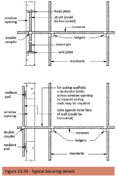
Fireplaces
Outline
Fireplaces offer many and varied options.
The choice depends on a number of factors; the following being the more common considerations:
- Heating requirements
- Functionality
- Aesthetics
In the past, the efficiency of a fireplace has usually been overlooked with the main emphasis based on a combination of the above three. However, with global warming and energy efficiency becoming more prevalent, the efficiency of a fireplace unit is now considered one of the more important deciding factors when wanting to use a fireplace.
Environmental considerations also need to be considered, in particular, whether the fuel being used is renewable, and how polluting it is, with many authorities declaring certain urban areas ‘smokeless zones’. The main purpose of a chimney flue is the removal of smoke and gasses from a fireplace.
The heat of a fire in a space warms the air, thus causing an expansion and a consequent reduction in density. The colder and heavier air in the room then forces the lighter air up the flue, also if the flue is the correct length it actually draws/sucks the air out. Smoking problems and a lack of chimney draught are often caused by poor chimney design and construction.
Considerations
There has been a steady reduction in the use of open fires over the last few decades. Firstly, the lack of skills in building a properly functioning brick fireplace has become non-existent. This in turn led to the introduction of the steel firebox being used to overcome this problem; the second issue lies in the efficiency of these open fires; they require that solid fuels be burnt as the primary source of heat. This raises a debate from an environmental standpoint, which is outside the scope of this book.
The point we would like to make here is to highlight the fact that open fires are inefficient, but provide an visual appeal that cannot be matched. And with a number of other types of fireplaces available on the market today, the specifier/ owner or builder needs to be aware of his or her options.
Types of fireplaces
Open fires
There’s nothing to beat the traditional open log fire in any environment. However open fires are generally energy inefficient as highlighted above, with much of the heat going straight up the chimney. The efficiency can be improved by fitting a convection type firebox that directs heat into the room and usually would have a damper fitted that offers some kind of draught control. As with most fireplaces the flue and chimney are critical to the overall efficiency.
Closed fires (slow combustion stove)
The combustion stove is essentially a firebox made of cast iron or steel in which wood is burned. These stoves are becoming increasingly popular in South African homes, and considering they have been used in Europe for decades it’s no wonder they are considered extremely efficient in these colder climates. The chimney and flue options are also more flexible than standard open fireplaces. The main benefit of cast iron is its high thermal mass and its excellent heat radiating characteristics, allowing the heat to be transferred evenly and for long periods after the fire has died down.
Gas fires
Gas is wonderfully clean and efficient. With the turn of a switch and you have an instant fire no mess no fuss. Many open (wood) fires can be converted to Gas. The chimney and flue requirements of gas units are a lot easier and simpler to detail and with the new “vent free’ types no flues are necessary. They adhere to strict CO2 (carbon dioxide) rates.
They are very efficient, with all the heat being pushed into the room. A vent free unit also uses about a third to half the amount of gas that a traditional gas fire would The above types of fireplaces are available in the following forms:
- Built-in – units need to be specified long before building commences, in order that the unit can be detailed to suit the design of the building and allowance made for the necessary structure surrounding the fireplace unit and the necessary structure required for the chimney and flue, and how it will exit the roof or wall; and any other special details required, like breast work, mantelpiece, hearth, gas connection etc.
- Freestanding – units also require the specifier to allow for their inclusion into the proposed structure; firstly for the optimum position required in a room and more importantly, where the flue can be best installed and how it will exit the roof or wall; and again any other special details required like the hearth. These types of units are also best suited for the renovation market or for secondary installation (after the building is built).
- Vent free – units allow the home owner the versatility of installation in almost any position as no flues are required. The units can be installed into existing cavities or into pre-manufactured casings as built-in or as drop-in standalone units. The trend to have a modern linear fire place as a focal point is far more of a statement than a source of heat.
Chimneys and flues
Flues and chimneys are basically ducts in and on buildings, which exclusively convey the gasses from fireplaces to the outside, typically over the roof. Almost all fireplaces require a flue and chimney; only new technology gas ‘vent free’ systems don’t require a flue. Provision should be made in the design of the foundations to support the weight of the fireplace, flue, and chimney. The effective recommended height of the flue from the smoke hood to the chimney mouth of an open fire should be greater-than or equal to 4.5m.
How a flue works
The up-draught or ‘pull’ in a flue results from a combination of the height of the flue and the difference in temperature between the flue gasses and the outside air. The column of hot gasses in a flue is lighter in weight than an equivalent column of cold air outside, so the pressure inside a warm flue is less than the air pressure outside. It is this small difference in pressure that creates the up draught and actually allows the chimney to function properly. And remember:
- The warmer and taller a flue or chimney the better the draught and the less risk of condensation It is important to take into account all requirements for the flue height, flue protection and the flue termination, before making a final decision on the location of the fireplace in the room.
Hearths
The hearth is best described as the floor of the fireplace. Hearths must be of a material that does not burn, such as brick, steel, or tiles, and should extend by a minimum of 300mm on either side of the fireplace and project by at least 500mm in the front and on the reverse side if using a doublesided fireplace.
Standards
Extracts from SANS 10400-V: 2010
Definitions
For the purposes of this document, the definitions given in SANS 10400-A (some of which are repeated for convenience) and the following apply.
Chimney
The part of a building, which forms part of a flue, but does not include a flue pipe.
Deemed-to-satisfy requirement
non-mandatory requirement, the compliance with which ensures compliance with a functional regulation
Dwelling house
Single dwelling unit and any garage and other domestic outbuildings thereto, situated on its own site
Dwelling unit
Unit containing one or more habitable rooms and provided with adequate sanitary and cooking facilities
Flue
Passage which conveys the discharge of a heat-generating appliance to the external air
Flue pipe
Pipe forming a flue, but does not include a pipe built as a lining into a chimney
Functional regulation
Regulation that sets out in qualitative terms what is required of a building or building element or building component in respect of a particular characteristic, without specifying the method of construction, dimensions, or materials to be used
Non-combustible
Classified as non-combustible when tested in accordance with SANS 10177-5.
Requirements
General
The functional regulation contained in part V of the National Building Regulations (see annex A) shall be deemed to be satisfied where the design and construction of any flue pipe, chimney, hearth or fireplace comply with the requirements of 4.2 to 4.4.
Flue pipes
No flue pipe shall be designed and installed in such a manner that it will cause a fire hazard to adjacent material. No flue pipe shall be connected to a shaft or duct, which forms part of a ventilation system. No flue pipe shall be installed in a shaft or duct in which services are to be situated which might be adversely affected by heat.
Chimneys
A chimney, which is within or is attached to a building, shall comply with the following requirements:
- It shall be designed and erected from non-combustible materials and in such a manner that it will not cause a fire hazard to adjacent material.
- It shall not be installed in a shaft or duct in which services are to be situated which might be adversely affected by heat.
- Combustible material, such as a timber floor joist, trimmer, or roof truss, shall not be built within 200 mm of the inside of a chimney.
- Where in a dwelling house or dwelling unit the walls of a chimney are made of masonry units, such walls shall be of solid masonry, and where such walls are less than 190 mm thick, such chimney shall be lined in accordance with 3 below, provided that such walls shall not be reduced to less than 90 mm in thickness.
- Notwithstanding the requirements of 1 above, the thickness of a chimney wall in a building covered by a combustible roof shall be not less than 190 mm.
- Where a chimney is provided with a flue lining, such lining shall be made of material, which will withstand any action of the flue gases and will resist, without cracking or softening, the temperatures to which it might be subjected, and it shall extend throughout the full height of such chimney.
- Where a chimney has either a laterally unsupported height greater than 4 m or a laterally unsupported height greater than four and a half times its minimum lateral dimension, it shall be designed in accordance with the requirements of SANS 10400-B.
- The height of a chimney outlet shall be not less than (see figure 13.60)
- 1 m above the highest point of contact between such chimney and the roof, provided that where a roof has an angle of slope on both sides of a ridge of not less than 10° from the horizontal and the centre line of the flue of the chimney is not more than 600 mm from the ridge, the height of such chimney outlet shall be not less than 600 mm above such ridge;
- 1 m above the highest point of a window or roof light capable of being opened or a ventilation inlet situated in a roof or external wall where the horizontal distance from the nearest point of such window, roof light or opening to a vertical line through the centre of such chimney outlet is less than 2,3 m; and
- 1 m above the eaves level in the case of a chimney which does not pass through the roof of a building but is within 1.5 m of the nearest wall of such building, provided that at a gable end of such building, such chimney shall extend not less than 600 mm above the highest point of such gable end.
Hearths and fireplaces
Every fireplace used for the burning of solid fuel shall have a hearth made of non-combustible material of adequate thickness. Such hearth shall extend not less than 500 mm in front of the grate or fire basket and not less than 300 mm beyond each side of such grate or fire basket. No timber floor joist or trimmer or any other combustible material shall be built into a hearth.
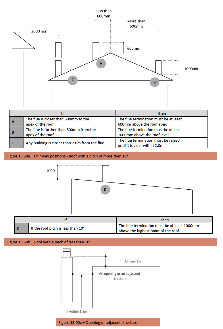
The Superstructure Process
Outline
The detailing of the superstructure or basically the walls as found on the drawings of buildings is a very important factor of the building (superstructure) process. The wall thicknesses, types, for example cavity walls, types of masonry units to be used, and any special bonds etc. all need to be established before any brickwork commences. These details also need to specify, things like; the building in of window and door frames and the types to be used, sills, lintels, reinforcement, services, walls supporting suspended floors and roofs, and what method of construction would be preferred at intersecting internal walls, raking back or toothing. This list only represents some common details required. The items listed under the previous heading ‘Brickwork’ would be a good starting point to use as a checklist, in ensuring the detailing has been thoroughly considered, and established before building work commences. Remembering every project usually has its own unique requirements.
Setting out
All dimensions and angles should be set out according to the drawings and to a level of accuracy appropriate to the type of building and its occupancy. It is also important to keep in mind that setting out should be such as to reduce the cutting of masonry units to a minimum. See Table “Planning and setting out guide” at the end of this section, which will assist in this process. All external walls and the position of corners and openings should be accurately established before brickwork commences. The first course should be laid with care as inaccuracies in level, plumbness, and alignment will only get worse as successive courses are laid.
Positioning Doors and internal walls
Carefully mark and measure internal walls and door positions using chalk lines. Place the door frame on top of the surface bed as required in line with chalk lines. Ensure you have positioned the door frame(s) to the correct hand when using steel door frames i.e. LH or RH; or have the rebate correctly positioned in the case of timber frames i.e. open in or out – a rule of thumb is that external doors should always open in. Make sure the frame is plumb in both directions. Attach board(s) to the head of the frame, and use bricks or blocks to keep board(s) in position at surface bed level (see figure 13.61; this keeps the frame in position, whilst the brickwork is being built-up.
Double check that the head (top) of the frame is level, then using a block or brick-course gauge (rod) mark courses on the door frame, starting at the top. See figure 13.62.
Note: These boards can only be removed once the brickwork has extended past the last lug fitted to the frame and the levels are checked.
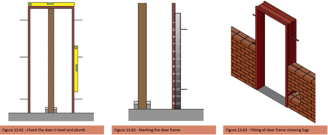
Building up walls
The first thing to do is to lay the damp-proof courses (DPC’s), which must be positioned to cover the full width of the wall including the plaster thickness (if plastering is specified), and should protrude 10 mm from the exterior face of the wall and be turned downwards. The DPC shall be laid with mortar above and below the membrane.
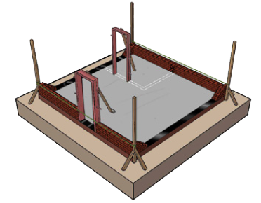
Start at the corners, by firstly positioning the corner profiles and then build up a number courses at each corner, and then lay masonry units between the corners. Keep checking the brick or block gauge and remember to move the gauge line up the corner profiles as the brick or block courses rise.
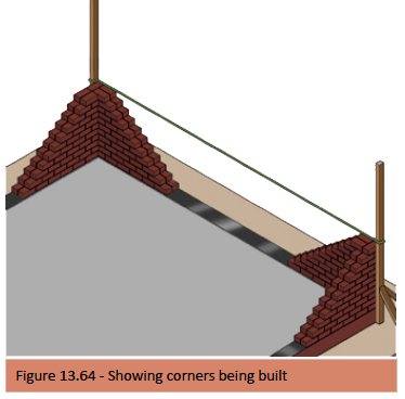
Where an internal wall is marked, lay one brick or block horizontally along the marking. Then lay the commencing courses with a step at the end of the wall, usually half the horizontal size of the masonry unit being used; the internal wall will then rise in height as the external wall rises in height. This raking back as it is known should not be raised above the level of the external or surrounding brickwork and by not more than 900mm at one lift. Although some of the following factors have been discussed previously, it is important we highlight their importance once again.
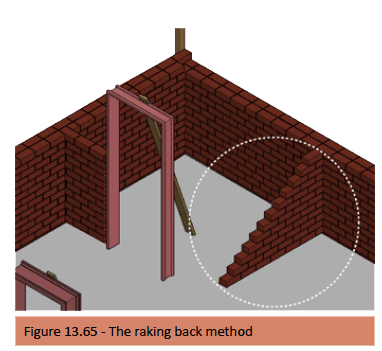
Bedding of masonry
Masonry units shall be laid on a bed of mortar in proportions as described under mortars (Dagha) and or as specified on the drawings. All perpend and bed joints shall have a nominal thickness of 10 mm Mortar should not be spread so far ahead of actual laying that it stiffens and loses its plasticity, as this results in poor bonding and weatherproofness.
Note: The consistency of the mortar should be adjusted to suit the degree of suction of the masonry units (IRA) instead of the units being wetted to suit the mortar.
Damp proofing
Damp proof courses shall be installed in accordance with the best practice as described under brickwork and not forgetting the significance of installing vertical damp proof membranes where any changes in floor level occur.
Bonding
Unless otherwise stated or specified, masonry units shall be laid in stretcher bond. Masonry units of dissimilar materials shall not be built into the same wall as described under brick properties and types.
Brick or bed reinforcement
Brickforce or bed reinforcement should be installed in accordance with what was discussed under brickwork – Brick reinforcement and Lintels.
With the following practical addition – Brickforce should be folded at the corners of a building, not cut, basically running the entire length of the wall. Where two ends of brickforce meet, they should overlap by about 300mm and tied together.
The only time brickforce should be cut is where it meets with a control or expansion joint. Wall ties or metal anchors (hoop iron) should be used in every second course at adjoining or cross walls, where the raking back method cannot be used (corners and where internal walls are joined).
Alignment and perpends
All brickwork or blockwork shall be built true and plumb. The courses shall be aligned and care taken to keep the perpends in line.
Reveals
The depth of reveals and rebates shall conform as far as possible to the masonry unit size being used, in order to maintain masonry strength and to avoid the cutting of masonry units.
Jointing and pointing
As the work proceeds, excess mortar shall be struck off the internal and external face of the wall and mortar joints on the face of the wall shall be compacted to provide a joint as specified. Tooling of the joint should be delayed until the mortar has stiffened slightly.
Positioning Windows
When drawing an elevation, one will measure a window from lintel height down. Practically, when building, the wall into which a window is being built will be built from the bottom up. In order to build to an accurate height, measure to lintel height, subtract the specified window height and build up to that point; but remember to leave space for the window sill, which is usually installed after the brickwork has been completed or before the plastering begins.
Once again, when fitting a window frame (for steel or wooden frames), ensure that the frame is at right angles, plumb, and level on top. As with door frames, use a board(s) fixed to the top of the fame and secured with bricks at surface bed level, to keep the frame in place while building the walls up around the frame continues.
See figure 13.66
Note: Windows are generally fitted in the middle of the wall.
Steel window frames come with lugs factory fitted; while in the case of wooden window frames, lugs (usually 150mm wire nails) are fitted on site as building commences, or the wooden frame can be fitted later and then screwed into the wall.
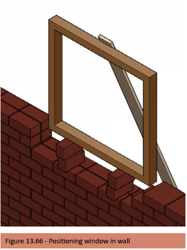
Lintels
Pre-stressed concrete lintels are commonly used in stock brick applications above openings, windows, and doors. While in face brick applications, the brick-on-edge method is often used, where no concrete lintel is fitted, although in some cases a lintel is fitted on the inside skin, above the brick on edge.
We have covered lintels extensively under brickwork mainly because this is one element that is often installed with little consideration of their structural value and long-term safety, leading to widespread and serious long-term consequences.
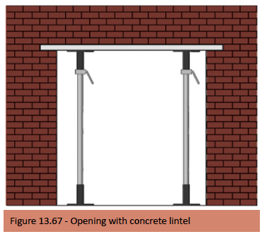
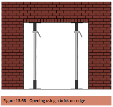
Arches
The theory of building arches is covered under brickwork; here we only illustrate the basic steps involved in the building of arches.
Note: Mortar for arches should be mixed separately and made stronger (more cement and the addition of a little riversand).
Step 1 – The centring is positioned over opening and held in place with wooden supports and cross bracing.
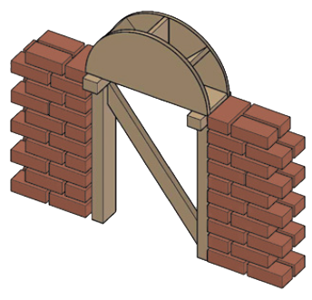
Step 2 – The brickwork is built up from either side.
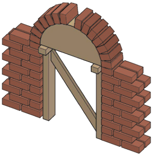
Step 3 – The final brick ‘the key brick or keystone’ is placed in the centre.
Building in roof anchors
Building in roof anchors to secure roof trusses, rafters, or beams shall be anchored into the wall with a galvanised steel strap or wire to extend into the wall as described under brickwork.
Fitting window sills
Window sills are normally installed after the brickwork has been completed and the scaffolding has been removed, so as to prevent the window sill from accidental damage. Two types of external window sill are commonly used; Fibre cement or Brick on edge. See figures 13.69
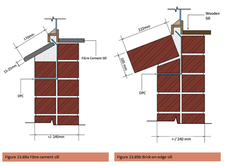
Chasing for services
Horizontal chasing of walls should be avoided where possible. Where chases, holes, and recesses are so made, ensure they do not to impair the strength or stability of the wall. Vertical chases in solid units should not exceed one third of the wall/leaf thickness and horizontal chases should not exceed one sixth of the wall/leaf thickness. Walls constructed of hollow units should not be chased at all and services should be located in the unit cores. Where chasing in these blocks is unavoidable, it should be no deeper than 15mm.
Planning and setting out guide
The standard nominal brick size for the common/ stock brick is – 222mm long x 106mm wide x 73mm high and when used with a recommend 12mm mortar joint: The format size becomes 234mm (horizontal) x 118mm (wide) x 85mm (vertical). Wall width will depend on the actual size of the masonry unit being used and on whether the wall is a single brick skin or in multiples thereof i.e. 2, 3 or 4 skins and on the joint width of the collar or cavity between skins – these dimensions added together will determine the overall width of the wall. The following table will assist in setting out the number of brick courses required for horizontal and vertical dimensions.

References
Alexander G C. 2010. Energy Saving Building Solutions. Johannesburg: Buildaid Publishing.
Alexander G D & Alexander G C. 2010. Buildaid Building and Pricing Guide 2010/11. Johannesburg: Buildaid Publishing.
Alexander G D & Van As F. 2008: Civil Technology. Johannesburg: EWA Publishing.
Cement & Concrete Institute – www.cnci.org.za
Clay Brick Association – www.claybrick.org.za
Concrete Manufacturers Association – www.cma.org.za
Harrison H W & de Vekey R C. 2002. BRE Building Elements – Walls, windows and doors. London: Construction Research
Communications Ltd.
Julyan E L. 1998. Building & Civil Technology. 2nd Edition. Johannesburg.
Kraukamp F W. 2001.Bricklaing & Plastering theory N1, first edition, seventh impression. Sunward Park. FW Kraukamp
Kraukamp F W. Bricklaying & Plastering theory N2. National Technical Certificate Part II.
South African Bureau of Standards – SANS 10400 Part’s A; B; C; K; XA & various other standards. Pretoria. SABS Standards
Division.
Van Amsterdam E. 2009. Construction Methods for Civil engineering. Cape Town: Juta & Co.
Van Amsterdam E. 2010. Construction Materials for Civil engineering. Cape Town: Juta & Co.