Chapter 15
ROOFING
Introduction
Terminology
Standards
Roof Construction
Roof Coverings
Fire Protection
Underlays
Thermal Insulation
Shading
Roofing Accessories
Flashings
Waterproofing
Introduction
Roofing plays a very important part of a building, not only aesthetically but structurally. It is important that a roof, whether flat or pitched, is designed and installed correctly. Rain and wind can play havoc with a roof that has been installed badly or to the incorrect manufacturers’ specification; for example, the incorrect pitch, the incorrect application, or poor workmanship.
With an age of diversity in the building Industry and the abundant choice of design and materials, one tendency has become very clear; the increasing complexity of the geometry of buildings, and more especially of roofs. It is therefore simple to deduce that defects increase in direct proportion to this increase in complexity of geometry of the surfaces of buildings; i.e. at the intersections of different planes and materials. Notwithstanding certain roofs suit only certain designs.
Added to this is the increasing lack of properly skilled artisans in erecting roof structures and the fitment of the desired roof coverings, associated fittings and accessories; highlighting the need for taking extra care in both design and construction, when it comes to roofing.
It is also an element which requires the supervision of an engineer. Local authorities will not issue occupancy certificate to a building without an Engineer’s certificate that the roof complies with the standards as laid out in the National Building Regulations.
One must consider that a roof has numerous functions other than aesthetics that need to be taken into account in the design and erection process:
- Protection from sun, wind and rain.
- Strength and stability
- Durability
- Control of heat gain and loss – insulation
- Prevention of condensation
- Fire protection and prevention
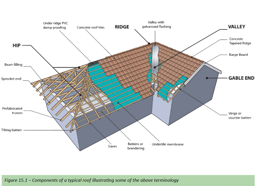
Terminology
Apex
The top of a truss (roof) where the two chords (rafters) meet.
Barge board
A barge board is a sloping roof trim fixed in lengths along the edge of a gable to cover the exposed timbers or as some describe as an ornamental board along the gable end of a roof.
Batten
Pieces of timber usually SA pine 38mm x 38mm or 38mm x 50mm laid and nailed across the top chords of the truss at 90° at a spacing to suit the roof covering but less than 540mm onto which the roof covering is fixed or hooked and typically used in roof slate or tile applications (see brandering).
Beam filling
See Superstructure
Bottom chord
The part of the truss that forms the bottom edge that joins the two heel joints and supports the ceiling – also called the tie-beam.
Bracing
The members fixed to several adjacent trusses usually at a 45° angle to make the roof stable and to prevent buckling of compression members.
Brandering
Same as battens but fixed to the bottom chord to support the celling (see batten).
Double Pitch
Trusses where the top chords (rafters) slope up to the apex at the same angles (pitches) from both ends of the truss.
Dual Pitch
Trusses where the top chords slope up to the apex at two different angles (pitch) from each end of the truss.
Dutch hip
A hip end where the end slope does not reach the apex but the top part of the hip forms a small gable; also called a louver hip.
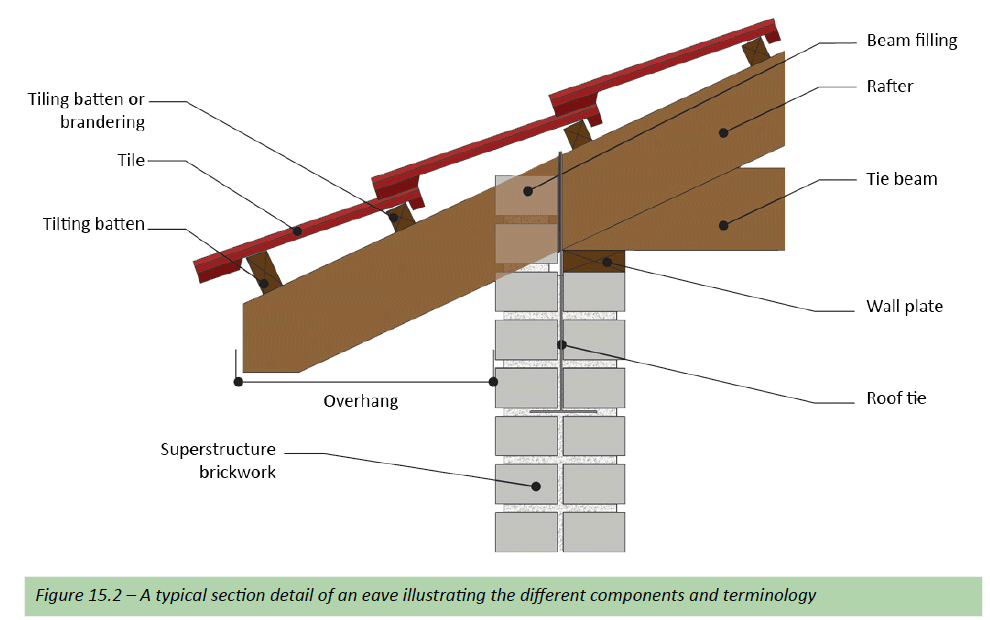
Eave
The under part of a sloping roof that overhangs a wall or a vertical surface (see overhang).
Fascia
A board or similar trim set on edge along the eaves to cover the rafter ends (sprocket ends) and can also carry a gutter, or a simple horizontal band that projects slightly from the wall surface below the edge of the roof.
Gable
A gable is the triangular upper part of a wall at the end of a pitched roof. There are different types of gable ends, and these relate to different architectural styles for example, Cape Dutch.
Gablet
Small gable on the roof slope, usually formed by a valley set.
Girder truss
A truss (single or multiple ply) used to support other trusses.
Hanger
A U shaped bracket made of light gauge galvanised mild steel used to support trusses on a girder or beam.
Heel
The truss end joint where the top and bottom chords connect, or where the end web joins the bottom chord in stub and mono-pitch trusses.
Hip
A hip is an outer intersection between two sloping surfaces of a pitched roof – water flows away from a hip.
Hurricane clip
A light gauge galvanised mild steel angle bracket used to fix two timber members at 90° to each other.
Insulation
Insulation in roofing is a material used to prevent heat loss and/or heat gain through a roof. The insulation membrane can also provide fire protection as well as a control against condensation (if correctly installed) in sheeted roof applications.
Jack rafter
The smallest end part of a hip corner construction using only single pieces of timber (loose rafter).
Jack Truss
The mono pitch trusses of the hip which are supported at the high end by the hip girders.
Mono Pitch
A truss where there is only one rafter slope.
Nib
Extensions of the bottom chord past the truss end, usually to support the truss in brickwork or on a truss hanger.
Overhang
The part of the truss top chord that extends past the truss heel. Measured horizontally from the truss heel, but from the outside wall face of the building.
Pitch
The angle of a roof as measured off a horizontal plane.
Plumb Cut
Top chord (rafter) overhangs are usually cut off vertical, to allow the fixing of fascia boards and/or a gutter at the roof truss ends (sprocket ends).
Polynesian
Trusses with a pitch change in each top chord from a lower pitch to steeper pitch going from heel to apex.
Portal frame
A frame of two columns with one horizontal roof beam between them, or two sloping rafters that join in the middle.
Purlin
These are pieces of timber usually SA pine 76mm x 50mm laid and nailed at 90° across the trusses or beams onto which the roof covering is fixed and typically used in sheeted roof applications.
Rafter
A sloping roof beam, usually from eave to ridge. The term rafter is also applied to all types of trussed rafter, the sloping beam of a portal frame, and the principal rafter of a truss – also known as the top chord.
Roof and roofing
A roof can be defined as the upper structure for and covering of a building, and roofing as the materials which form that covering.
Ridge
The horizontal line on top of a pitched roof (the apex) usually covered, for example with ridge tiles.
Spacing
The distance between the centres of two of the same elements, i.e. trusses.
Span
The span is the distance between two supports (usually walls) onto which a truss or beam rest.
Stub end
Also called a stub heel; where the top and bottom chords are some distance apart and connected by the first truss web.
Tie beam
The bottom horizontal member of a roof truss equal in length to the span of the roof – also known as the bottom chord.
Tilting batten
Also known as a tilting fillet; the tilting batten is the last batten at the bottom edge of the rafter. It is larger than the battens and usually 76mm x 50mm and sometimes cut to triangular shape in cross-section. It lifts the end of the last tile or slate.
Top chord
Also called a rafter; the part of a truss, which forms the top edge usually at a slope and has the battens or purlins fixed to it to carry the roof covering.
Truss
A truss is a rigid structural framework of timbers or steel members bridging a space with each end of the truss resting on some form of support, usually walls. The trusses provide support for battens or purlins which in turn support the roof covering, e.g. roof tiles. Trusses are often prefabricated and brought to site, but can also be built on site.
Underlays
Underlays can be fitted under the tiles or roof covering to assist with waterproofing should the concrete tile or other roof covering fail; the underlay can also act as an insulating membrane or vapour barrier. An underlay in roof tile applications is also used to prevent dust from entering the ceiling/roof space.
Valley
A valley is an inner intersection between two sloping surfaces of a pitched roof – water flows towards a valley.
Vapour barrier
Impervious barrier that prevents the passage of water vapour through building components.
Verge
The sloping edge of a pitched roof above a gable. A verge can overhang or be flush with the wall.
Wall plate
A piece of timber usually SA pine 76mm x 38mm placed flat on top of the supporting wall (completed brickwork) on the inside skin acting as a flexible and bearing surface for the trusses or beams to be placed and fixed and to spread the load.
Webs
The truss members that connect the top and bottom chords together.
Standards
Extracts from SANS 10400 Part L: Roofs
SANS 10400 establishes general requirements for satisfying the National Building Regulations issued in terms of the National Building Regulations and Building Standards Act, 1977 (Act No. 103 of 1977), and some of these requirements that are deemed to satisfy the following parts of such Regulations of Part L: Roofs are highlighted below:
L1 General Requirement
The roof of any building shall be so constructed that it will:
- a) Resist any forces to which it is likely to be subjected
- b) Be durable and waterproof
- c) Not allow the accumulation of any rainwater upon it surface, and
- d) As part of a roof and ceiling assembly provide adequate height in any room immediately below such assembly.
LL3.3
The requirements of subrules LL3.4 and LL3.5 shall apply only to single or double pitched Howe-type trusses, with a span of not more than 10 m, supported at heel joints only and having bays of equal lengths of not more than 1.5 m.
LL3.4
- (a) Where the roof covering is of the class given in column 1 of Table 11.1 the size of rafter (top chord), tie-beam (bottom chord) and the grade of timber to be used shall be selected from such table in such a way that the desired truss span does not exceed the relevant figure for maximum truss span given in column 4, 5 or 6, as the case may be.
- (b) All web members shall be not less than 38 mm x 114mm Grade 4 timber.
- (c) Where rafter and tie-beam sizes are to be determined from Table 15.1, the slope of the roof shall –
- (i) be not less than 15° nor more than 30° for Class A or Class C covering; and
- (ii) be not less than 17° nor more than 35° for Class B covering.
Commentary
Table 15.1 may seem confusing or even incorrect since the same nominal timber sizes appear to be capable of supporting either a Class A (light) or a Class B (heavy) roof covering and in the case of the heavier covering, greater truss spans are permitted. This apparent anomaly is negated when this table is read in conjunction with subrule LL3.6 (see below), as the centre-to-centre spacing of trusses supporting Class B roof covering is limited to a maximum of 760 mm compared with 1400 mm for Class A roof covering. The load per truss for a roof supporting a Class B covering is therefore less than that for a truss supporting a Class A covering.
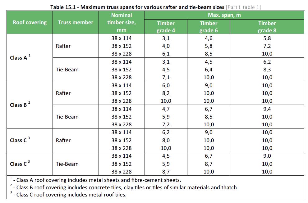
It would appear from the table that in certain cases the use of a better grade timber is of no advantage as it does not lead to any increase in the maximum span that is permitted. The figures have been included in order to complete the table but the restriction on span is artificial in the sense that it is not directly related to the capability of the timber. The fact that no span of more than 10m has been included in the table serves only to draw attention to the fact than any roof supported on walls complying with the rules contained in Part K of SANS 10400 is restricted to a maximum span of 10m. It is also important to note that the values quoted in this table should only be used subject to the further limitations that –
- (a) the truss configuration is that of a Howe-type truss (see fig.15.4) and the maximum span is limited to 10 m;
- (b) the slope of the roof is –
- (i) more than 15° and less than 30° for Class A or Class C roof covering; or
- (ii) more than 17° and less than 35° for Class B covering.
It is always permissible to use a roof slope outside the range with Table 15.2 but as in any other case where it is desired to depart from the limitations on the use of Table 15.1, a rational design of the proposed truss, including calculations, must then be submitted to the local authority. It should be noted that factory manufactured trusses employing metal plate connectors, although commonly used in house construction, do not generally comply with the requirements of Table 15.1. Design data, if required, can be obtained from the manufacturer of such prefabricated truss.
LL3.6
The centre-to-centre spacing of trusses relevant to the roof covering to be applied shall not exceed:
| Class A | |
| Sheets, either metal or fibre cement | 1400mm |
| Class B | |
| Concrete tiles, clay tiles or tiles of similar material | 760mm |
| Metal tiles | 1050mm |
Roof Construction
Outline
Roofs used in domestic and small commercial buildings are usually constructed by using timber roof trusses and/ or rafters and in certain applications timber poles. While in larger commercial and Industrial buildings, portal frames or girders using steel are more commonly used.
The need for taking care in the design, the construction and erection of roofs and fixing of the roof covering is essential to insure water penetration into the interior of the building is avoided. There is an absolute requirement in roof construction to prevent water reaching the interior of a building and where two kinds of rainfall intensity need to be considered:
- Rain falling vertically
- Rain driven by wind
Both categories contribute to the total quantities of rainwater needing disposal, but the second category particularly affects the weather tightness of lapped roofing, such as tiles and slates, and even the direction and extent of lap of larger sheets; with many manufacturers recommending the use of underlays, fixing of tiles etc. in these applications.
One must remember that rain falling while the wind is blowing affects pitched roofs more than flat (and walls even more so), it is therefore important to consider ones geographical location, associated weather patterns and not only your desired roofing requirements when deciding on an appropriate roofing design. Roofs can be flat or pitched and are made up of a variation of elements, types and shapes.
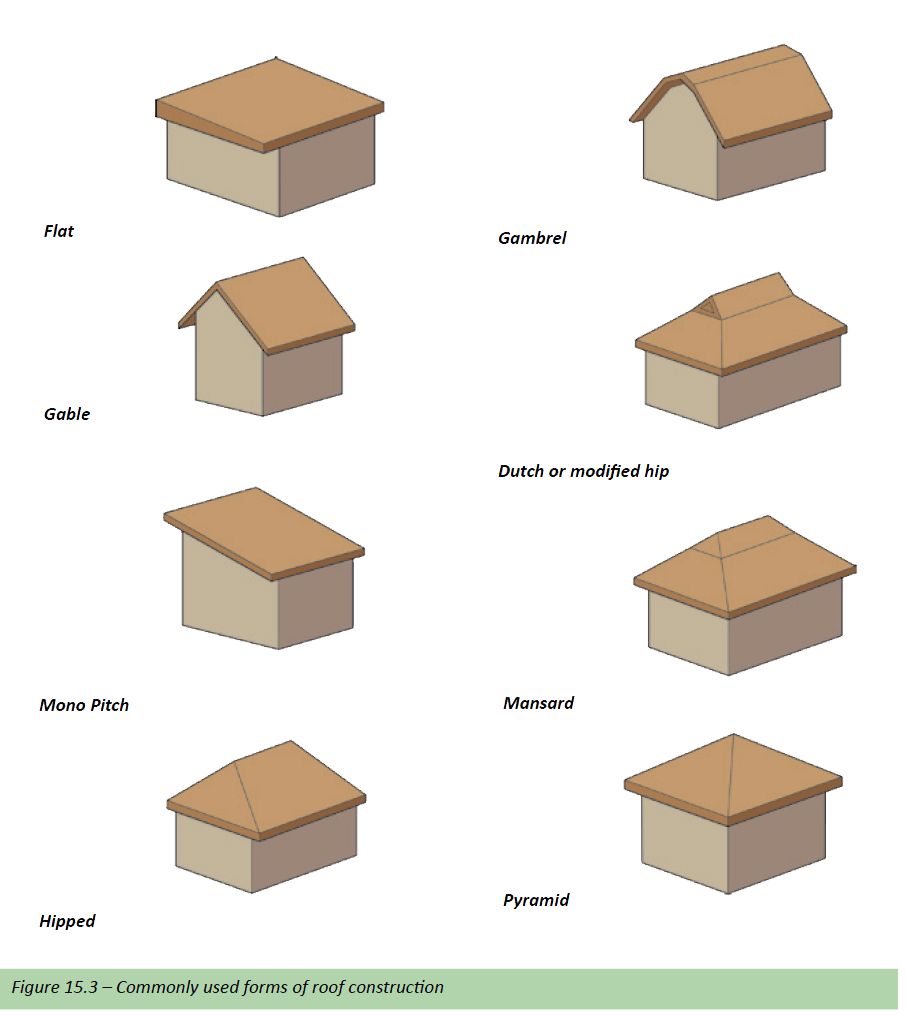
Roof Forms
The most commonly found forms of roof construction include the following:
Roof trusses
A roof truss is a coplanar (forces lying in the same plane) assembly of structural members made from timber or steel joined at their ends. The diagonals form triangles, producing a rigid framework. Triangulation is the fundamental concept behind the design of a roof truss; a triangle is the only multisided geometric figure that is rigid and will not move or rotate provided a structural member doesn’t bend or a connection (join) fail.
Roof trusses act like beams and support a roof and all imposed loads. A roof truss consists of top and bottom chords and a system of webs. The slope of the top chord (the pitch) can vary as required to suit the roof form, design and roof covering.
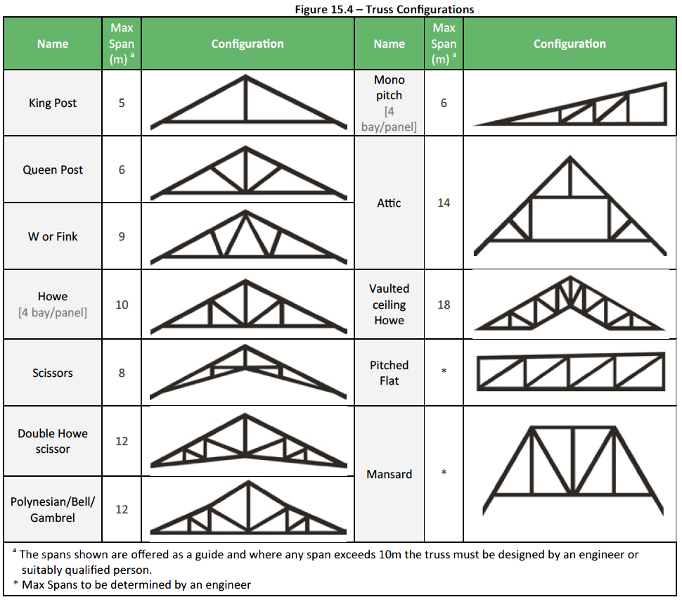
Truss Configurations
Some of the more commonly used truss configurations are illustrated in figure 15.4 below.
Timber Trusses
Timber trusses are widely used in the construction of roofs and for all types of buildings. They can be easily erected on site, are relatively easy to handle and can span the width of most buildings without interior load-bearing walls being required.
Site made trusses
Roof trusses manufactured on site must comply with the minimum “deemed to satisfy” requirements for nailed and bolted trusses of SANS 10400 or be designed by a professional engineer or other competent person.
Some local authorities will require an engineer’s certificate for the roof truss construction before issuing an occupancy certificate and similarly some financial institutions won’t make final payment without an engineer certifying the roof construction.
The requirements of the National Building Regulations are that the truss, single or double pitch, shall be a ‘Howe’ type truss (see figure 15.4) with a span not exceeding 10m for double pitch trusses and 6m for single pitch trusses.
The trusses must be supported at heel joints only and have bays of equal lengths not greater than 1.5m.
Then depending on the class of roof covering, the size of the rafter (top chord), tie-beam (bottom chord) and the grade of timber to be used it must be selected from table 15.1 in such a way that the desired truss span does not exceed the relevant figure – see LL3.4 under standards above.
For more on timber grades and sizes see the next sub-section on materials.
The spacing of site made roof trusses must be in accordance with SANS 10400 Part L: Roofs – LL3.6 – as described under standards above.
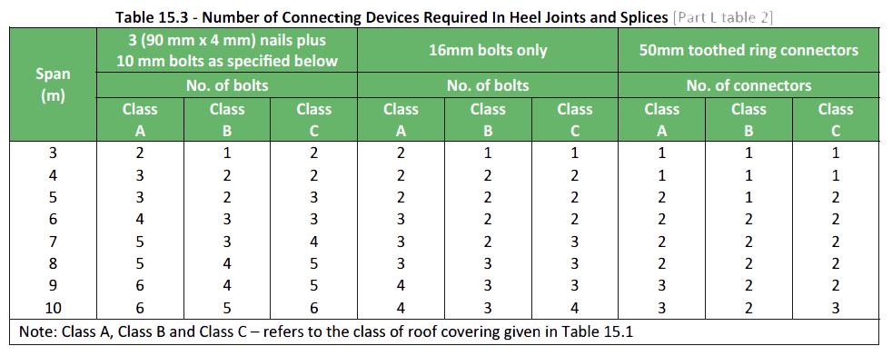
The number of connecting devices to be used at each intersection between two members at any heel joint or any splice in a site made truss shall be determined from table 15.3. In the case of any joint other than a heel joint or splice, one 10mm bolt plus four clinched 90 x 4mm nails shall be used.
To ensure a high standard of finish, it is essential that the roof structure is properly constructed. Poor workmanship and warped timber will reflect on the finished product and may result in deflection and distortion of the roof.
- Select a level surface to work on.
- Set out the first truss according to the span and pitch of the roof.
- Mark out the timber for the various members of the truss and cut accurately.
- Assemble the truss by nailing and bolting through the two thicknesses of timber and clinch the nails over on the reverse side – (see table 15.3).
- The bolts must have a washer on the nut end as the cup head pulls tight into the timber.
- The completed truss can now be used as a jig for the construction of the remaining trusses of the same size.
Prefabricated trusses
A network of prefabricated timber roof truss manufacturers can be found throughout South Africa. These fabricators operate under licence to suppliers of nail-plate connectors and use computer design programs devised by professional engineers. These fabricators are trained and equipped to offer advice and solutions for any shape of roof, any pitch or span for new structures, or to match existing roofs and since they are carefully engineered and factory built, prefabricated trusses have a consistent, reliable quality.
For the purposes of municipal approval (when required), design calculations can be issued, together with the appropriate roof layout, truss diagrams and any explanatory notes that may be needed.
When placing orders with a truss fabricator, or when a quotation is required, the fabricator must be provided with the following minimum information or given a detailed roof drawing covering the following:
- Overall span of roof
- Eaves overhang
- Pitch of roof
- Cantilever distance (if any)
- Roof covering
- Ceiling materials, plus any special loads
- Geyser position and capacity
- Other details which may affect the design e.g. solar panels
In most instances the truss fabricator would make a site inspection prior to manufacture of the trusses, to ensure dimensions and building work match that of the drawings originally provided.
Materials
Structural timber suitable for all normal building work is covered by SANS 1783-2004, which defines visual stress grades and mechanical stress grades. The compulsory grading of timber prescribes that under grade structural sized timber is clearly marked with black crosses (known as black cross) on both ends to distinguish it from graded timber bearing the appropriate SANS mark for the various visual grades.
In order to obtain the permissible stresses, stress grades are adjusted by means of the appropriate modification factors which relate to the specific conditions of use. Structural timber can be used to its full safe load-bearing capacity, and hence more economically, in engineered structures if it is stress-graded. S5 is the most commonly used on site timber; and S7 or mechanically graded timber is used for engineered designed prefabricated trusses.
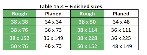
Finishes
Timber is available in three different types of finish, to suit specific applications;
- Rough Sawn or
- Sized or
- planed
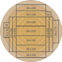
Rough sawn timber (RGH)
Timber sold as rough has no further planing done to it after milling; also known as fine sawn. Structural sizes 38×152,
38×228, 50×152, 50×228 and 76×228.
Sized timber
Structural sizes 38×38, 38×50, 38×76 and 38×114 are generally sold as “Sized”. These products have been planed slightly to a consistent size to allow accurate truss manufacture and exact framing of buildings. The afore mentioned sizes are generally planed to 36×36, 36×47, 36×73, 36×111.
Planed timber (PAR)
Is a smooth finish which suits certain applications e.g. exposed trusses requiring painting. Planed timber has to be ordered as the process involves rough or sized timber, placed in a planing machine which then planes each side of the timber. As planing reduces the size of timber a decrease in strength can be expected.
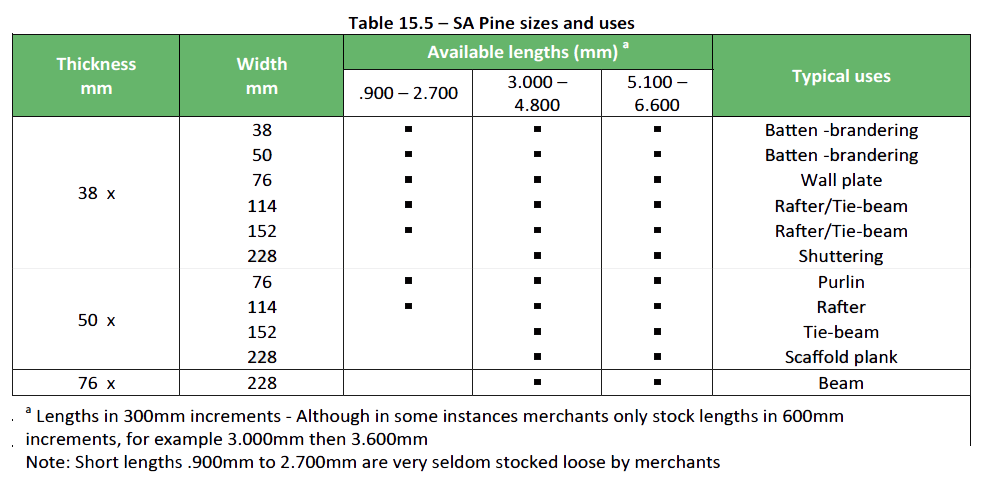
Sizes
Generally, the SABS allow a +3 -2mm tolerance on the thickness of rough sawn, kiln dried SA Pine. The lengths could be up to 50mm longer than that stated. 0.900 to 2.700 metre lengths are referred to as short lengths and 3.000 to 6.600 metre lengths as long lengths; which are also priced differently to that of short lengths. Lengths longer than 6.600 metres are available as finger- jointed timber.
Steel Trusses
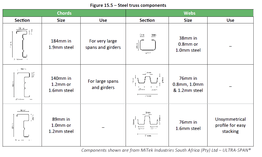
A number of steel truss systems are available for roof construction. Included are roof trusses, open-web joists and space frames. Open-web joists are a type of truss. They are light-weight structural members made from steel angles and bars. They, like other trusses, are end bearing and can span long distances in roof construction. Space frames are a three dimensional truss system. They provide a structural frame that spans in several directions and over large areas with a minimum number of vertical supports (columns). Steel trusses consist of top and bottom chords and a system of webs. Steel trusses are manufactured using galvanized mild steel and depending on the system and manufacturer.
the material sizes and thicknesses differ quite considerably. Steel trusses are designed and usually prefabricated although for low-cost housing or geographically remote projects steel trusses can be supplied in kit-form and assembled on site. The biggest advantage of using steel is that it is lightweight and compact which improves handling and erection on site and is economical to transport. Another is the span capability of steel where clear spans of up to 40metres are possible. Lastly steel is non-combustible and is more suitable for certain applications. Some examples of steel truss components showing sizes are illustrated below:
Rafters and Beams
The difference between a rafter and beam in roofing is a matter of description and use. A rafter is a sloping roof beam typically in timber, which is fitted from eave to ridge and used in place of roof trusses for aesthetic reasons by design or purpose. Whereas a beam can be described as a structural member that carries a load and can be in timber or steel. Rafters can also be described as girders, joists or bearers, the latter describing supports for a suspended floor. Beams can also be used to carry timber trusses or poles and are then built into the structure (walls) of the building and/or spanned between columns to support a roof. Materials used for rafters and beams Timber Laminated beams Laminated beams can be used for beams and rafters as their properties provide to carry greater loads and spans (up to 15 meters) than that of normal structural pine and are available in the following popular sizes – these sizes can vary slightly from manufacturer to manufacturer.
- Thickness: 35, 45, 70, 102, 140 mm
- Depth: 147, 231, 297, 330, 363. or up to 990 mm in 33 mm multiples
- Finish: PAR. or Fine Sawn
- Use: Internal & External Use. (Should be specified)
Rafters
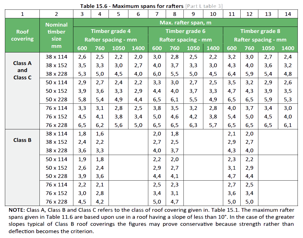
Extract from SANS 10400 Part L: Roofs
Where rafter construction is used in place of roof trusses and the roof covering is of the class given in column 1 of Table 15.6 the size of rafter and grade of timber to be used shall be selected from such table in such a way that the rafter span does not exceed the relevant figure for maximum rafter span given in columns 3 to 14, as the case may be. Where rafter spacing differs from that in Table 15.6, intermediate values of maximum rafter span may be interpolated within the range of values given, for the relevant timber grade.
Steel
Steel is an alloy of carbon and iron, which is hard, tough, elastic, and capable of resisting various stresses and loads. Mild steel is the most popular steel used for general structural beams used in roofing. Steel sections come in a number of different shapes and sizes and the most popular sections used in roofing are the I-Beam; Channel; Angle Iron and T-Section. We have only highlighted these components very briefly in the section as timber is the more commonly used material used in residential and smaller type commercial buildings.
Note: For more on steel sections and sizes see Metalwork section.
Timber Poles
Commonly referred to as ‘Gum’ poles from the Eucalyptus (Gum) tree from which poles are cut. (Eucalyptus – Grandis/Saligna)
Round poles are typically used, for the timber frame construction of thatched roofed buildings. They are of course used for many other applications e.g. Props, fencing, bearers, pergolas etc. Timber poles and associated products are available untreated but are usually treated in one of the following:
- Creosote or
- CCA or
- TBTO (Tanalised) or
- Flambor (preservative and fire retardant (Boron based preservative)
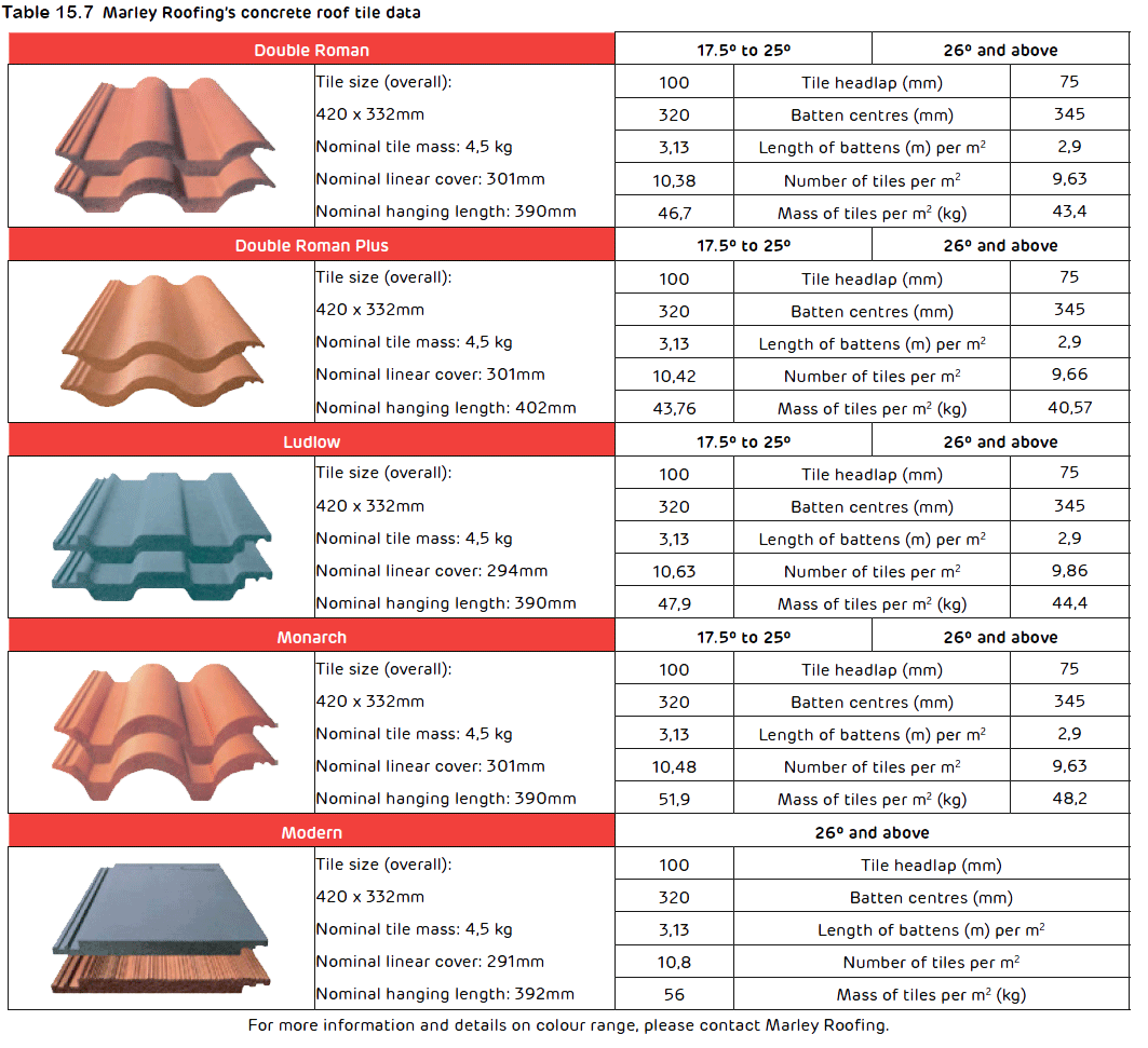
Benefits of Marley Roofing’s Concrete Roofing Solutions
- Longer lasting – Marley Roofing’s concrete roof tiles continue to strengthen over time and this is why concrete roofs that were constructed more than 40 years ago are still intact today.
- More variety – The raw materials and pigments used in the manufacture of roof tiles lend themselves to a number of distinctive tile designs to choose from
- Strength and durability – Moisture, which can undermine other building materials through rust or rot, has no weakening effect on Marley Roofing’s concrete roof tiles.
- Low maintenance – Marley Roofing’s concrete roof tiles are inert and compact, meaning that they won’t lose their key properties over time and therefore require less cleaning or repainting.
- Affordability – Double Roman “Plus” is a lightweight roof tile which does not compromise the properties or quality of the product, catering for the needs of the price-conscious customer.
- Eco-friendly – Marley Roofing’s roof tiles are recyclable and manufactured through environmentally-conscious processes to reduce the environmental impact through all stages of the roof tile’s lifetime.
- Energy Efficient – Superior thermal efficiency is obtained through insulated concrete.
Nail lengths for different tile profiles
- Monarch – 90mm
- Double Roman – 75mm
- Double Roman “Plus” – 75mm
- Ludlow – 63mm
- Homestead – 63mm
- Modern – 50mm
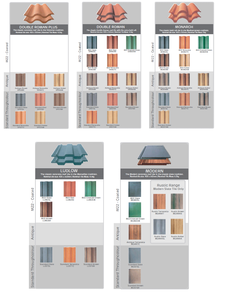
Inland Tile Range
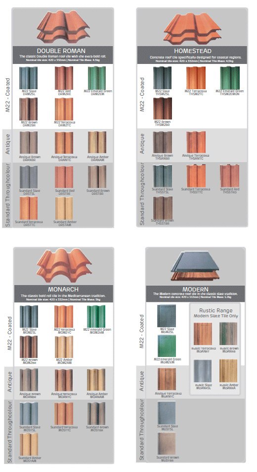
KwaZulu Natal Tile Range
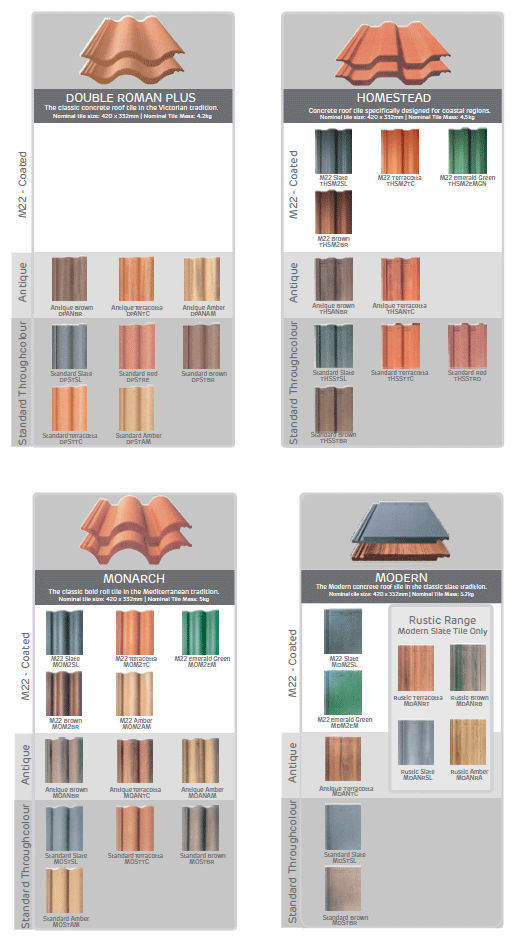
Western Cape Tile Range
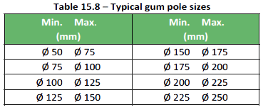
Sizes
Round Poles are available in the following diameters from nominal Min. diameter to Max. diameter.
Available in lengths starting at 1.800m up to 7.800m – in 600mm increments. Longer lengths are available up to 13.000m
Slabbed and split poles
Poles can be slabbed one side or two sides to various thicknesses between sides or split longitudinally. Split poles typically coming from the off cut created in producing the slabbed pole or what is commonly called a bearer. Available in diameters from 75mm up to 250mm and engths from 1.800m up to 7.200m.
Saplings/Laths
Laths or saplings serve the same purpose as battens and are used for tying/fixing thatch in thatch roof applications; also used for fencing and decorative applications. Available in diameters from 15mm up to 30mm; and in lengths from 1.800m up to 4.500m.
Roof Coverings
Outline
The following sub-sections discuss briefly the various types of roof coverings in common use; also showing the three different classifications of roof covering as described in table 15.1.
Roof Tiles
Concrete (Class B)
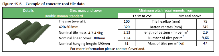
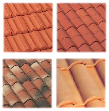
Concrete roof tiles are a common and cost effective form of roof covering. Concrete roof tiles consist of a mix of cementitious materials, such as Portland cement, sand, hydraulic cements, fly ash, pozzolans, fine aggregates and pigments, producing a durable lightweight tile that is fire resistant. Some are pigmented in the mix process known as ‘through colour’, others are coated after moulding.
Concrete roof tiles are manufactured in an extensive range of profiles, colours and finishes (finishes will vary from one manufacturer to another) which enhance the visual appearance of any roof and provide designers with a wide scope for expression.
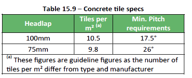
Concrete tile specifications
Truss and rafter centres when using concrete roof tiles are spaced to a maximum of 760mm using 38 x 38mm battens – refer Standards LL3.6.
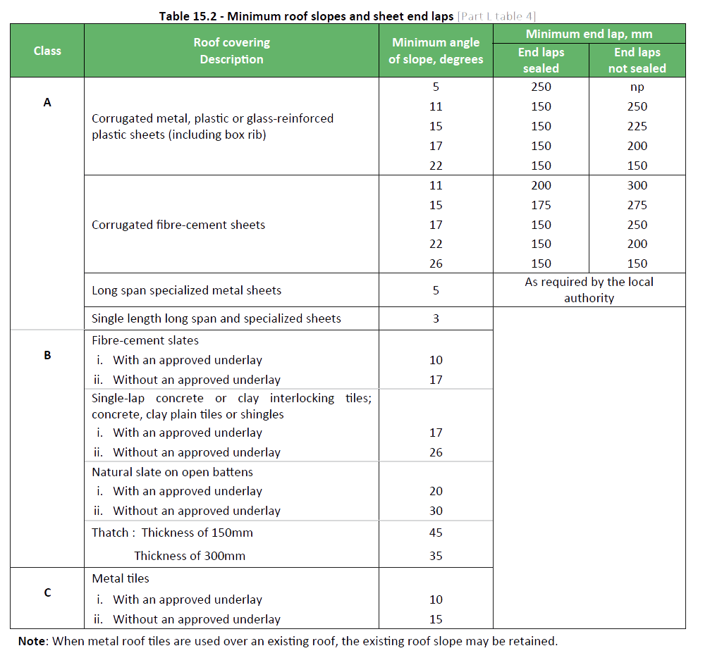
Underlay – a suitable underlay is in all cases recommended. Modern practice has demonstrated that the underlay is a fundamental part of a tiled roof at pitches below 26° and for pitches above 45°, and at all pitches in exposed and coastal areas. (See underlays later in this section for more information)
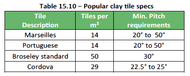
Clay (Class B)
Clay roof tiles enhance warmth and character to a building with permanent colour which weather and age over time, but never fade. Clay roof tiles are natural and durable which elegantly enhances the appearance of roofs, not only withstanding the elements, but actually improving with age from exposure.
Clay roof tiles are available in the ever-popular Broseley, Constantia & Cordova as well as the cost effective Portuguese and Marseilles. They are available from various different manufacturers in South Africa, in various colours like terracotta and multi flashed colours. Various bonds are used when laying different types of clay tiles, from; Straight bond or mock interlocking, broken bond, flat and semi-circular over under; the over-tile and under-tile are of roughly the same shape, the under-tile being larger; these tiles form a beautiful roof which is flexible in both sidelap and headlap.Truss and rafter centres when using clay roof tiles are the same as that of concrete roof tiles.
Clay cover tiles
Clay cover tiles are usually used to cover IBR or Brownbuilt roof sheeting, to provide an attractive covering when low roof pitches are required. They can also provide thermal insulation and acoustic benefits. In certain instances it is required that IBR roof sheeting be covered with a cover tile by local authorities.
The truss and rafter centres when using cover tiles over sheeted roofing will reduce from the maximum of 1 400mm as directed by the cover tile manufacturer.
Pressed Metal (Class C)
Pressed metal roof tiles are strong and light weight which significantly reduces the quantity of timber required in the support structure and provides easy installation. They allow for ease of delivery and don’t require large trucks to transport them, making this a popular roof covering in remote lying areas. A further advantage being steel-based, no breakages occur during transit or storage on site.
Metal roof tiles come in different profiles and finished with either a standard acrylic coating or a textured coating and available in various colours and are also manufactured from different materials.
Due to their lightweight attributes, tiles are the ideal application
in the re-roofing market where they can be laid over the existing
roof without removing the old roofing material. Truss and rafter centres when using pressed metal tiles are spaced to a maximum of 1 050mm using 38 x 38mm battens – refer Standards LL3.6. Pressed metal tiles can be used without underlay on roof pitches between 15° and 45°; and with underlay with pitches from 10° to 15°.
Sheeted Roofing Systems
Sheeted roofing systems come in various different profiles, e.g. corrugated, IBR and folded steel. And manufactured from numerous different types of material to suit specific applications, all having certain advantages and unique properties with metal sheeting being the most commonly used.
Metal (Class A)
Metal Roof sheeting is available in a wide variety of profiles, thicknesses and types of material and coatings. Usually all roof sheeting materials are manufactured from hot-dipped galvanized steel and fall within internationally accepted specifications and tolerances.
Other types of material are manufactured like Supergalm which is an aluminium zinc alloy coated steel and Zincalume® a composite of aluminium and zinc. Typical types of material include; Commercial quality, high tensile and econogalv, while types of coatings include Chromadek. There is a variety of sheeted roof systems designed for larger type commercial buildings like shopping centres and industrial buildings known as ‘concealed fixing’ or ‘standing seam’ roof systems and are quite different to ‘exposed fixing’ roof sheets used for smaller type buildings and residential buildings. We have concentrated more on the pierced/exposed fixing systems used in residential building projects and only provide a brief overview of concealed fixing systems.
Pierced/exposed fixing
IBR and Widespan sheets must be laid with one corrugation and corrugated sheets with one and a half corrugations, side lap with the narrow flute uppermost and should be fixed through the crests of alternate flutes to purlins – see figures on next page (all fixing holes should be drilled and not punched).
Truss and rafter centres when using metal roof sheeting are spaced to a maximum of 1 400mm using 76 x 50mm purlins – refer Standards LL3.6.
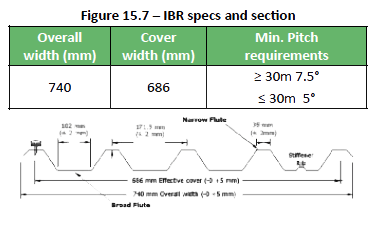
IBR
The name IBR is abbreviated from ‘Inverted Box rib’ and has become a household name in the South African building industry. The deep, broad flute design offers excellent drainage characteristics combined with optimum weight versus load/span capabilities.IBR sheeting has a square fluted profile usually with an effective covering width of 686mm designed for use as side cladding or roofing material in commercial, industrial and domestic applications.
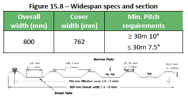
Widespan
Widespan is a roofing and cladding profile designed to provide an economic alternative to deeper Box rib profiles without losing the aesthetic appeal of a square fluted sheet profile. The widespan profile offers greater spans and lower roof pitches than corrugated sheeting but provides the same covering width, being 762mm.
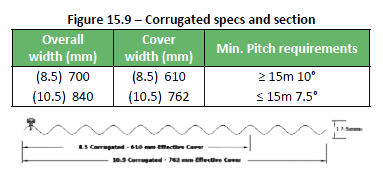
Corrugated
Corrugated (iron) is the traditional and familiar S-Rib profile for roofing and cladding applications. It is the oldest and most commonly used roofing profile because it is easy to handle, has excellent fixing properties and commensurate strength. The S-Rib is derived from the sinus curve and offers strong structural properties. The 8.5/76 represents 8.5 corrugations over the width of the sheet and the 76 refers to the distance in millimeters between two consecutive curves. The overall width of a traditional 8.5 corrugated sheet is 700mm and a 10.5 corrugated sheet is 840mm.
Concealed fixing
Concealed fixing is where a clip or special cleat is fixed to the purlin which securely holds the sheets in position and usually lock-in both the sidelap and centre ribs of the sheet; or where the cleat fastens to the purlin and folds over the flanges of the sheet and a cap snaps over this assembly. The main advantage of this type of roof system over others is the water-tightness achieved with very long spans at low pitches. Another advantage with concealed fixing (standingseam) is corrosion and failure at fixing points is eliminated. Brownbuilt metal sections pioneered the manufacture of concealed/secret fix roof profiles in SA with their “Brownbuilt” profile. Today other types of profiles are available and manufactured by a number of different manufacturers.
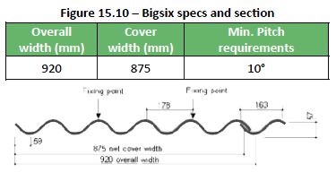
Fibre Cement (Class A)
Fibre cement roofing sheets essentially consist of an inorganic hydraulic binder or calcium silicate formed by a chemical reaction of a siliceous and a calcareous material, reinforced by natural synthetic organic fibres. The sheets are supplied in their natural grey colour and can be painted (where required) with a 100% acrylic PVA after installation. Tinted sheets using a ultra-violet resistant pigment and branded as ‘Vineyard’ sheets are also available and recommended for Tuscan roofs where they are used as underlay for clay tiles.
Fibre cement roof sheeting is available in two basic profiles;
- Bigsix and Victorian, which have been used in the South African building Industry for roofing applications and side cladding for decades.
- Bigsix corrugated sheets are durable and lightweight that can be used in all sectors of the building industry for roofing and side cladding.
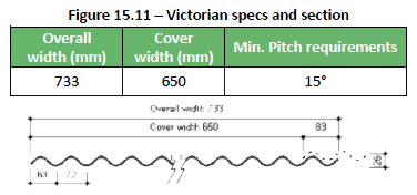
The Victorian sheet is a popular profile and it has been designed to recreate the appearance and character of a traditional Victorian style roof and with its reduced dimensions and mass, makes handling and laying relatively easy. Victorian sheets are particularly suitable for coastal areas where corrosive conditions prevent the use of many other products.
Organic Fibre (Class A)
Onduline is an extremely tough lightweight corrugated roofing and wall cladding material manufactured from bitumensaturated organic fibres under intense pressure and heat. It is flexible, economical and virtually indestructible. It provides a high degree of weather protection and thermal insulation- even in the most extreme climatic conditions. Colour stability is also ensured through a unique pigmentation process which “stains” the colour into the sheet.
- Needs virtually no maintenance
- High insulation and sound absorbency values
- Cannot rust or become brittle
- Rot and fungi resistant.
- Colour impregnation minimizes colour loss
- It is impact resistant and easy to handle.
- Easy to cut, shape and fix
Translucent (Class A)
Translucent or GRP (Glassfibre reinforced Polyester) sheeting is manufactured using UV stabilised unsaturated polyester resin and glass fibre reinforcement material. The weathering surface is covered with a highly UV stabilised gelcoat layer. This new generation technology offers superior weathering characteristics to conventional methods of surface protection in the GRP sheeting industry.
GRP products are specifically designed to withstand the harsh South African climatic conditions and a range of colours are manufactured, with the more popular being clear, white (opal 50), green and blue. All the generally used profile shapes, to match those of other roofing and cladding materials are usually manufactured.
Roof Slates
Slates can be described as any rectangular sheet of roofing material, whether of natural slate, stone, cast stone, fibre cement, or metal.
Fibre Cement (Class B)
Fibre cement roofing slates essentially consist of an inorganic hydraulic binder or calcium silicate formed by a chemical reaction of a siliceous and a calcareous material, reinforced by natural synthetic organic fibres. Fibre cement roof slates offer designers and specifier’s an alternative to other slates with a modern clean look and are available in a number of bright colours including white.
Fibre cement roof slates are designed for a minimum roof pitch of 10° using and underlay and 17° without and underlay and in high wind areas the slates may no longer provide a waterproof covering and a waterproof underlay must be installed. It is however important to be aware of the fact that any distortion or unevenness in the roof structure and/or battens will reflect in the final appearance of the application. Time spent to ensure that the structure and battens are accurate and sound is therefore a small investment in the process of achieving an excellent result.
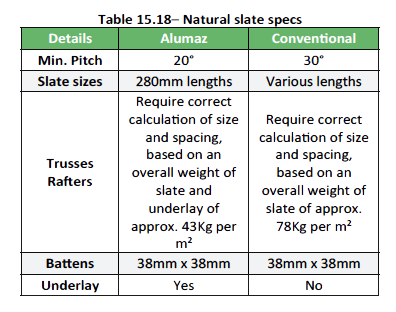
Natural Slate (Class B)
Slate is commonly described as a dark grey natural stone made up of many thin layers which can be split (riven) into thin sheets, then cut to size to create tiles. Slate is a heavy material and the roof structure must be designed to carry the weight – see Table 15.18. Slates are fire resistant and have a long life but are more costly than most other roofing materials.
Marley Roofing’s Fibre Cement Roof Sheets
Features and Benefits of Marley Roofing’s P75 Fibre Cement Roof Sheets:
- The product is non-combustible, rated A1
- The product causes minimal interference with radio wave transmissions
- Noise resistant
- Easy to install with normal tools
- Corrosion resistant
- Environmentally friendly – no harmful substances escape into the environment during production
- ASBESTOS FREE – sheets are made of concrete, limestone, amorphous silicon dioxide, cellulose, water, mineral additives and synthetic fibres (PVA)
- The product is “breathing”, enhancing ventilation and durability, and resisting condensation
- Long lasting, weather resistant and durable
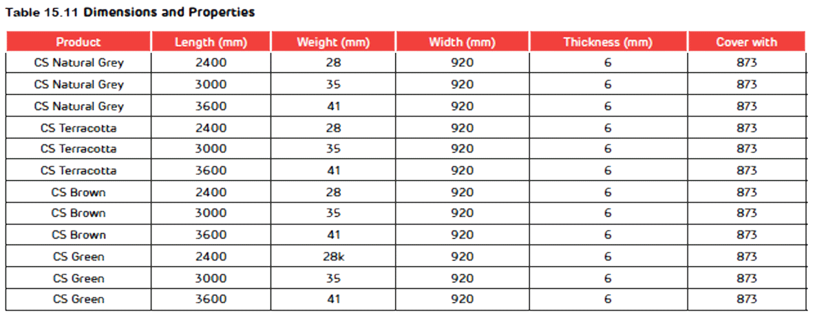
Dimensions and Properties
Refer to Table 11.49.
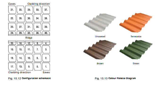
Standard Colours
Refer to Fig 11.12.
Fixing Accessories
Wood: Pozigrip screw with PVC washer (dimensions: 6.3mmx120mm)
Steel: Hook bolt and nuts – length determined by depth of steel purlin (+90mm)
Minimum Installation Guidelines
- Minimum pitch: 10 degrees
- Overlaps must be mitred
- Differences in height of overlays can result in roof leakages – to avoid this, two sheets are cut (mitred)
- Sheets are laid from right to left, and from bottom to top (for high wind areas, consult a structural engineer)
- According to the right-to-left cladding approach, the upper right and lower left edges must be cut
- Sheets can be cut with an angle grinder fitted with a masonry or diamond blade
- It is recommended that a 5-10mm gap be left between the upper right and bottom left sheets
- After cladding the upper left sheet, roof cladding should appear smooth
- Purlin size and spacing will be determined by the roof truss manufacturer (pitch, rafter spacing and clear span determine purlin space, however the minimum specified is 50x70mm wood with rafters 800mm apart and a clear span of max. 1400mm)
- Holes must be drilled not punched – drilled holes should be 2mm larger than the screw/bolt to allow for movement
- All fixing should be at least 25mm away from the edge of the sheets, and only in the crowns
- Do not exceed more than 300mm on the wall overhang and 150mm on the gable overhang
- The substructure must be leveled and squared out prior to installation for best results
Storage and handling
Storing sheets:
- When handled, sheets must be lifted at both ends
- Sheets must be stored in a covered room, away from rainfall
- Sheets must be stored on a dry, smooth and stable platform
- Maximum pallet stack: 2
Pallet Sizes
Refer to Table 11.50.
Handling sheets:
NOTE: Although Marley Roofing’s P75 FC Roof Sheets are fitted with security strips that can prevent a person from falling through the roof during roof maintenance works, it is recommended that duckboards are used as walking areas to avoid damage to sheets and injury to workers as per legislative requirements.
- Recommended Safety, Health and Environmental (SHE) regulations should be observed
- At no point should an area that has already been laid be used as staging for the next area
- Appropriate non-slip shoes should be worn by workers during roof maintenance installation
Marley KALSI®
Features and Benefits of Kalsi FIbre Cement Boards
- 100% ASBESTOS FREE
- Resistant to rot, termites and rodents
- Impact resistantancy on 9mm and 12mm boards
- Accepts most aesthetic and architectural finishes
- Moisture and humidity resistant
- Non-combustible
- Dimensionally stable
- Easy to install and handle
- Different board thicknesses available allowing for flexibility in use
Kalsi Ceiling
Dimensions and Properties
Refer to Table 11.51.
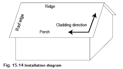
Installation Guidelines
Considerations:
- 4mm Ceiling boards are serrated (nail-up) and not suitable for plaster skimming
- 6mm Ceiling boards are ideal for exterior ceiling, soffits, car parks, laundries, bathroom, laboratories, etc.
- 6mm Ceiling boards are screw-up (brass wood screw, countersunk) – suitable for plaster skimming
- Use a sharp object to cut the surface of the board
- Hold board firmly and snap off
- Use H-Profile strips between boards (4mm or 6mm metal strips)
- Use one H-Profile strip per Kalsi ceiling board
Rafter Spacing
Refer to Table 11.52.
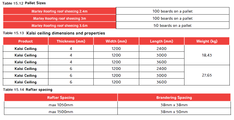
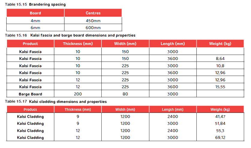
Brandering Spacing
Refer to Table 11.53.
Refer to Table 11.53.
Fixing Accessories
32mm x 2.5mm serrated ceiling nails must be placed 150mm away from the edges of the board OR 12mm x 40mm brass woodscrew with countersunk head
Dimensions and Properties
Refer to Table 11.54.
Kalsi Fascia and Barge Boards
Suitable for virtually any roof (includes tiles and sheeting), providing a functional finish while protecting the roof’s substructure.
Installation Guidelines
- Finishing is subject to the quality of the substructure (square and level)
- When the space between the rafters exceeds 900mm, a backing structure must be added
- The product can be nailed but fixings close to the edge must be pre-drilled (following the 25mm rule)
- Both wings of the barge board must be fixed in high wind and storm areas
- Hardened fluted steel nails or 12mm x 40mm brass wood screws with countersunk heads can be used for fixing
- Joint must not be made on fixing points but between them
- A support batten is needed if the span between rafters
Kalsi Cladding
These boards can be used as a facade system or for cladding in a lightweight steel frame (LWSF) structure. Boards can be fixed as an expressed joint system or flush plastered.
Dimensions and Properties
Refer to Table 11.55.
Installation Guidelines
- Fascia and barge boards can be joined by a cover strip or butt jointed (3mm gap sealed with specialised silicon)
- Boards can be plastered using specialist products and applicators
- A level and squared out substructure will ensure a quality finish
- Boards can be cut with an angle grinder fitted with a masonry cutting disc or a diamond blade.
- The max horizontal distance between the vertical supports should not exceed 610mm
- The max vertical distance between supporting brackets should not exceed 1500mm
- Thermal Conductivity for the cladding is 0.25 W/mk
- When boards are used in LWSF application, SANS 517 regulations must be observed
- – The cavity between two skins must be ventilated and insulated where applicable.
- – Sandwich specifications applies (Fire Proof, Acoustics, Thermal)
- – Board must be fixed every 300mm
- – Holes must be pre-drilled and countersunk
- – Hole must be drilled 2mm bigger than fixing shaft to allow movement in boards
Quality Assurance
All fibre cement products sold by Marley Roofing are warranted against defect in material and manufacturing processes. This warranty does not apply to defects resulting from any distributor or customer actions, such as mishandling, misapplication and improper installation. Our factories are also ISO 14001 certified, demonstrating our ongoing commitment to minimising waste, energy consumption, water consumption and pollution to the environment.
In addition to various international certifications, Marley Fibre Cement adheres to SABS specifications SANS 802 and SANS 10904.
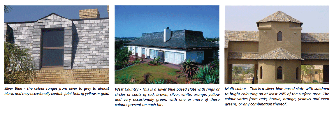
Natural slates are available in a number of different sizes and in a variety of colours usually originating out of the rock from which it was quarried; below are the more commonly used colours. See colours to the right. Slates are usually applied over solid sheathing covered with bitumen saturated roofing felt underlayment; commonly referred to as the Alumaz system. Slates can also be laid conventionally with no underlayment known as the conventional system.
Shingles
Shingles are made using an organic felt base saturated with bitumen and coated with a mineral-stabilized coating of bitumen on both sides. The exposed top side is coated with mineral granules. They are flexible, robust and lightweight and available in a range of colours.
Tile strips are available in a variety of styles, most common are rectangular and oval and they are laid on a boarded roof deck. Shingles can be laid on roof pitches of between 12° and 60°.
Roof Decks (flat roofs)
Construction methods for commonly used roof decks related to materials and types of construction are detailed in other sections in this book. A properly functioning roof depends on a structurally sound deck that is compatible with the roofing system and the installation of an approved waterproofing system.
Thatching
Thatch is classified as a class B roof covering and is probably the oldest type of roofing still used today. It is a popular and indigenous solution in particular areas where materials and skills are available and is the roof covering of choice in many African bush lodge designs and applications.
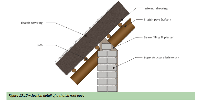
Thatch roofs should be constructed at a minimum angle/pitch of 45°. If good quality, clean, dry grass is used, the lifespan of the thatch will be increased (in general the top layer of thatch will need to be replaced and dressed every 12 to 15 years). Techniques, and to some extent materials, vary according to locality or region, and it is not possible in this section to provide more than an outline of what a thatch roof should contain.
- All changes of plane of the thatch surface; for example in valleys and over dormers, should be as gentle as possible.
- Thatch performs best on interrupted roofs and careful consideration should be given where to position chimneys or any other structure protruding from the roof.
- In thatching the interior finish forms an integral part of the overall roof design and needs to be discussed with the designer and building owner in the planning phase. As certain requirements could involve the services of a structural engineer e.g. Rafter/pole centres.
- Treatment of poles – normal dark poles or clear timber treatment.
- ither the same grass being used for the roof or a specific reed or thin bamboo.
Thatching is a natural insulator; cool in summer and retaining maximum internal heat in winter. Thatching also creates a relatively low cost means of additional living areas. The required pitch of a thatched roof allows this space to be used for a loft, by simply building a slab or suspended floor. The greatest disadvantage of thatch is the fire risk, although fire prevention in thatch has developed over the years and includes items like:
- Installation of a fire drenching system with either manual or automatic activation and is designed to deliver a thorough drenching to the roof exterior in the event of a threat of fire; installed into the ridge or capping.
- Dipping of the thatch into a fire proof solution before the thatch is laid. Or alternately spraying the roof with a fire retardant solution after the roof is complete.
- Using organic fibre simulated thatch, which is fire proof. Finally the installation of a lightening conductor is always advisable, however they can be seen as an eye sore and some insurance companies will cover your insurance needs without the installation of a lightening conductor.
Fire Protection
Outline
The designer of a roof of a building needs to know a lot about the conditions that will be imposed on that structure in service. Factors such as loading, environment and durability all have to be understood and assimilated into the design process, and considered in relation to behaviour in fire. For example, firewalls or fire stops that restrict the spread of fire in a roof assembly must extend continuously from a structure’s foundation to or through its roof.
If the fire wall stops at the roof, the roof assembly must then consist of non-combustible materials. The fire wall should be able to remain intact even if the structure on either side collapses due to fire damage.
The National Building Regulation’s fire protection standard – SANS 10400 Part T stipulates requirements for fire ratings and approved non-combustible materials; and contain content that is relevant to roofs and their fire protection – see some extracts below.
Extracts from SANS 10400 Part T: Fire Protection
- 4.12.1.2 Where any combustible roof covering material, including thatch, shingles and bituminized felt on boarding is used and the plan area of such roof is more than 20m2, the distance between the building so covered and any boundary of the site on which such building is situated shall be not less than 4,5 m.
- 4.12.1.3 Where any roof covering includes individual, small areas of combustible material, the total area of which is not more than 5 % of the roof area, and where:
- a) No such individual area is more than 20m2, such roof covering shall not be considered a combustible roof covering, provided that
- Where the slope of the roof does not exceed 60° there shall be a minimum distance of 1m between any two such areas, and
- Where the slope of the roof exceeds 60° there shall be a minimum distance of 1m measured horizontally and 3m measured along the slope of such roof between any two such areas.
- b) Any such individual area exceeds 20m2 in a roof and might constitute an element of danger to the public; such material shall be permitted only where it is the subject of a rational assessment regarding its use and application.
- a) No such individual area is more than 20m2, such roof covering shall not be considered a combustible roof covering, provided that
- 4.12.1.6 Where roof space is formed between any ceiling and any roof covering, such space shall be divided by means of non-combustible fire stops with a stability and integrity rating of at least 20 min into areas of not more than 500m2. The distance between such fire stops shall be not more than 30m, provided that this requirement shall not apply where such roof space and the room below are protected by a fixed automatic fire-fighting system and smoke control system in accordance with 4.4.2. If any combustible materials are installed in such roof space, such as combustible insulation, then the area for non-combustible fire stops shall be not more than 250m2 and the distance between such fire stops shall not be more than 20m.
4.12.2 Thatched roofs
- 4.12.2.1 The safety distances derived from 4.2 shall, notwithstanding the occupancy classes (see section 3 – Building Drawings – for this table), be based on a high fire load where the thatch is untreated and value A in the formula will be based on the facade area of the roof. Where the thatch is treated with an acceptable fire-retardant system, the safety distances shall be based on the following fire loads:
- a) test result A – low fire load
- b) test result B – medium fire load
- c) test result C – high fire load
Note: A test result C is equivalent to an untreated roof.
-
4.12.2.2 Notwithstanding the requirements of 4.12.1, a thatched lapa that has a roof plan area of less than 20m2, that is free standing and not attached to any other building shall not be erected closer than
- a) 1,0m to any boundary, and
- b) the safety distance from any building derived from 4.2, unless a free-standing masonry or concrete wall that has a height greater then 0,3m above the bottom line of the roof and which extends at least 1,0m on either side of the lapa is erected.
Note: Safety distances or fire separation specifies the distance between adjacent buildings; it is used to reduce the risk of fire spreading from one building to another.
- 4.12.2.3 A competent person (fire engineering) shall perform a rational assessment to determine the acceptability of erecting a lapa against an existing building.
- 4.12.2.4 Buildings and lapas with a thatched roof plan area greater than 300m2 or which are closer than the greater of 4,5 m to any boundary and the safety distances from an existing building derived from 4.2, shall be provided with additional fire protection systems (post-treated on both sides, pretreated as a permanent system or any other system) that are acceptable in relation to the actual roofing system that is to be used, and retreated and maintained at the intervals as indicated by the manufacturer of such systems.
Underlays
Outline
An underlay can be described as any layer or sheet material layed under another material. Typically a roofing underlay is a weather-proofing membrane, which prevents moisture, wind and dust entering the roof space. Roofing underlays can at times be confused with insulation, although in some cases they can perform dual functions, for example alububble® where the underlay is an effective water vapour barrier under roof tiles or roof sheeting and at the same time insulates the roof. Underlays for supported sheeting applications like shingles are usually of inodorous felt while tiles and slates are underlain with plastic sheet known as undertile plastic except on low pitches (typically in natural slate applications) bitumen felt is used.
The National Building Regulations covers various types of roof coverings and pitches where underlays must be used; they all fall under class B roof coverings as described in the table below.
Discussed ahead are the two types of underlay most often used in roofing applications; plastic and felt. For other underlays used for insulation properties, see thermal Insulation.
Plastic Membranes
Plastic underlays are a polyethylene membrane that has been specially formulated for use under roof tiles and slates, usually (250μm – micron) in thickness and made in rolls of 1.5 x 30 m and must be SABS approved.
The membrane is designed to prevent moisture from warm damp air reaching and condensing on ceiling boards and other vulnerable points in the building fabric. It is also used for the prevention of draughts and dust penetration into the roof space through tiles and slates, and prevents damage to ceilings and rotting of timbers.
The underlay further prevents strong wind from lifting and ripping off roof tiles. The underlay must be fixed horizontally between rafters and battens with 150mm minimum overlaps and carried well into the gutters. Avoid allowing the underlay to sag and form water traps – particularly behind fascia boards. A strip of underlay, at least 600mm wide, must be placed at hips so as to overlap each side for its full length. A similar strip must be laid for the full length of each valley ensuring that the opposing slopes overlap the edges.
Felts
Felt underlays are a sheet made from cellulose fibres of organic materials such as kraft paper and glass fibres saturated with bitumen and coated with a layer of thin mixed asphalt and crushed gravel or sand which can be laminated with other materials like aluminium foil or polyethylene. Felts are usually supplied in rolls of 10m and 20 m x 450mm and 900mm wide. In natural slate roofing applications the felt underlay is typically faced over half its width with a heat laminated layer of aluminium foil, used as a waterproofing membrane which is long lasting and also prevents the ingress of dust.
Vapour barriers
Vapour barriers are a plastic or foil sheet that resists diffusion of moisture through the roof assembly and typically used in sheeted metal roofing applications to prevent moisture from penetrating other inaccessible building components and condensing as moisture on insulation and ceilings. If condensation occurs in a building it is both difficult and costly to eradicate so it is always recommended to take precautionary measures during construction and design. To avoid condensation in a roof, moist air must be prevented from contacting the underside of the sheeting.
Thermal Insulation
Outline
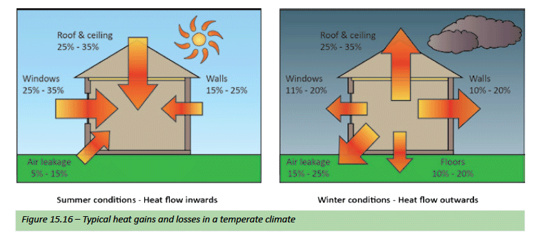
Thermal insulation acts as a barrier to heat flow and is essential in keeping a building or home warm in winter and cool in summer. A well-insulated and well-designed building or home will provide all year comfort. Climatic conditions will influence the appropriate level and type of insulation; which are covered in SANS 204 under Standards and in the “Insulation installation” section that follows. It is important to establish whether the Insulation will be predominantly needed to keep heat out (summer) or in (winter) or both. Insulation must cater for seasonal and daily variations in temperature. Ceilings and roof spaces account for 25 to 35% of winter heat loss and must be well insulated. To prevent heat loss, locate most of the insulation next to the ceiling as this is where the greatest temperature control is required.
Choosing Insulation
Insulation products come in two main categories – bulk (cellular) and reflective. Examples of Bulk insulation are – Mats e.g. Aerolite; Loose fill e.g. Thermguard; and Insulating boards e.g. Isoboard (polystyrene). They have many tiny air or gas bubbles, which reduce conductivity and commonly make them lightweight. Whereas reflective insulation, such as aluminium foils and low-emissivity coatings, reduces heat loss or gain by radiation. These are sometimes combined into a composite material. There are many different products available, like alububble®.
See next sub-heading ‘Insulation types and Properties’
To compare the insulating ability of the products available look at their R-value, this measures resistance to heat flow – the higher the R-value the higher the level of insulation.
Note: Products with the same R-value will provide the same insulating performance only if installed as specified.
R-values can differ depending on the direction of heat flow through the product. The difference is generally marginal for ‘bulk’ insulation but can be pronounced for ‘reflective’ insulation. Some products must be installed professionally while others can be defined as DIY – some types of insulation require the use of masks and protective clothing. Ensure products chosen or specified suit the particular application and will fit within the space available. The appropriate mass or amount of insulation depends on a number of factors like climate, building type and size, and whether the building is naturally or mechanically ventilated. The National Building regulations – SANS 10400: PART XA sets out minimum requirements – see Standards.
Insulation Types and Properties
Bulk insulation
Bulk insulation mainly resists the transfer of conducted and convected heat, relying on pockets of trapped air within its structure. Its thermal resistance is essentially the same regardless of the direction of heat flow through it. Bulk insulation includes materials such as glasswool, wool, cellulose fibre, polyester and polystyrene. All products come with one material R-value for a given thickness.
Reflective insulation
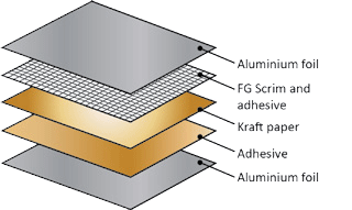
Reflective insulation mainly resists radiant heat flow due to its high reflectivity and low emissivity (ability to re-radiate heat). It relies on the presence of an air layer of at least 25mm next to the shiny surface. The thermal resistance of reflective insulation varies with the direction of heat flow through it. Reflective insulation is usually shiny aluminium foil laminated onto Kraft paper and or plastic (polyethylene or polypropylene) and reinforced using a scrim, all bonded together and available as sheets (sarking). Together these products are commonly known as reflective foil laminates or RFLs – See following example.
Dust settling on the reflective surface will greatly reduce performance. Face reflective surfaces downwards or keep them vertical. The antiglare surface of single sided RFLs should always face up. The Total R-values for reflective insulation are supplied as up and down values. Total values depend on where and how the reflective insulation is installed. Ensure system values provided by the manufacturer relate to your particular installation situation – See thermal resistance of systems below. Composite bulk and reflective materials are available that combine some features of both types.
Thermal Resistance of Systems
Manufacturers of bulk insulation products typically quote the thermal resistance, R-value and thermal conductivity, k-value and thickness, of their products. Confusion arises when suppliers of reflective insulation quote thermal resistance values which are inclusive of air gaps. Such thermal resistance values are in fact the resistance of a total system and cannot be compared to individual product R-values. RFLs, e.g. foil laminates, are typically very thin with high thermal conductivities, and thus have a very poor thermal resistance. For this reason, radiant barriers should always quote an associated air gap.
A word of caution must be sounded with respect to air gaps. Although it is acknowledged that static air is a very good insulator owing to its very low thermal conductivity, it must be borne in mind that thermal gradients can induce natural convection, in which case convection becomes the main mechanism of heat transfer and not conduction. When this takes place, the thermal performance of air gaps is drastically reduced. Many published system thermal resistances for reflective insulation ‘systems’ are based on ‘trapped’ air gaps above and below the barrier, which is sometimes impossible to achieve in practical installations. Thus thermal resistance values, inclusive of air gaps, determined under ideal, experimental conditions, tend to overstate the performance of the system. It is recommended that the total thermal resistance of systems be calculated on the basis of internationally accepted standards and procedures to ensure that the required thermal performance is achieved and can be guaranteed.
Where to Install Insulation
Firstly it is important to understand that roofs and ceilings work in conjunction when it comes to insulation and for this reason are referred to as roof assemblies in building standards.
- Install insulation under the roofing material to reduce radiant heat gain.
- Install insulation above the ceiling to reduce heat gain and loss. In most cases ceiling insulation is installed between the joists. (See: Insulation Installation).
- Install insulation in hot climates under veranda roofs where outdoor living spaces are used extensively, to reduce radiant heat gain. Heat build-up under verandas not only affects the space below but can affect conditions inside the house.
- Install insulation in bulkheads (sections between ceilings of different heights) to the same level as the ceiling, as they are subjected to the same temperature extremes..
Note: One can save up to 45% on heating and cooling energy with correctly specified and installed roof and ceiling insulation.
Improving Insulation in Existing Buildings
Many existing buildings were built before even basic thermal insulation provisions were introduced and many before any standards were considered or discussed. There are considerable opportunities for improving energy efficiency in existing buildings. These opportunities depend upon how individual buildings are constructed both for the practical difficulty of carrying out the improvements and their cost effectiveness.
Insulation can be added to existing buildings with varying effectiveness and cost depending on the construction type and where the insulation is being placed.
It is usually easy to insulate pitched roofs with accessible roof spaces, giving highly cost effective results. Flat roofs are more difficult to insulate as the space between ceiling and roof covering is often inaccessible and where the internal ceiling or external roof sheeting must be removed before insulation can be installed; which in most cases would not be cost effective. Although, it is possible to apply special coatings on the roof covering which does then provide better insulation. In so far as concrete slabs are concerned inverted insulation can be installed, which could be more cost effective when the waterproofing needs to me renewed.
Standards
Extracts from SANS 10400XA
- 4.4.5 Roof assemblies
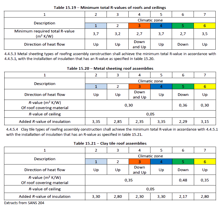
- 4.4.5.1 A roof assembly shall achieve the minimum total R-value specified in table 15.19 for the direction of heat flow.
- 4.4.5.2 A roof assembly that has metal sheet roofing fixed to metal purlins, metal rafters or metal battens shall have a thermal break consisting of a material with an R-value of not less than 0,2 installed between the metal sheet roofing and its supporting member.
- 4.4.6.2 Thermal insulation
Insulation shall comply with minimum required R-values and be installed so that it:- a) Abuts or overlaps adjoining insulation, or is sealed,
- b) Forms a continuous barrier with ceilings, walls, bulkheads or floors that contribute to the thermal barrier, and
- c) Does not affect the safe or effective operation of any services, installation, equipment or fittings.
4.4.6.2.2 Thermal insulation material shall be either;
- a) Non-combustible when tested in accordance with SANS 10177-5, and may be installed in all occupancy classes; or
- b) Classified as combustible according to SANS 10177-5, shall be tested and classified in accordance to SANS 428 protocol for its use and application.
4.4.6.2.3 Reflective insulation shall be installed and supported:
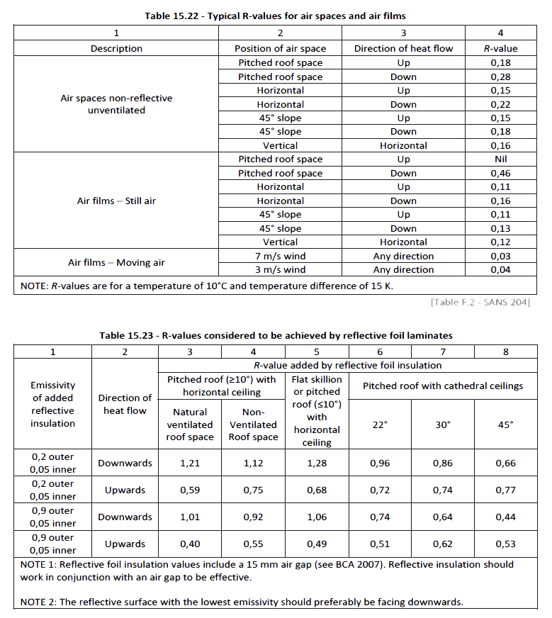
- a) With the necessary airspace in accordance with Table 15.22 in order to achieve the required R-value between a reflective side of the reflective insulation and a building lining or cladding,
- b) With the reflective insulation tightly fitted and taped against any penetration, door or window opening, and
- c) With each adjoining sheet of roll membrane being
- 1) Overlapped by not less than 100 mm, or
- 2) Taped together.
4.4.6.2.4 Bulk insulation shall be installed so that
- a) it maintains its position and thickness, other than where it crosses roof battens, water pipes or electrical cabling, and
- b) In ceilings, it overlaps the wall member by not less than 50 mm or is tightly fitted against a wall where there is no insulation in the wall.
The R-value of reflective insulation is affected by the airspace between a reflective side of the reflective insulation and the building lining or cladding. Dust build-up reduces R-values. Table 15.23 gives typical R-values for reflective insulation in specific circumstances.
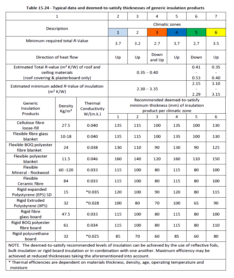
Note: See table 15.24 regarding typical R-values for roof/ceiling construction and the resulting typical intervention insulation thicknesses.
Example
Climatic zone: The first fundamental matter that needs to be determined before applying the DTS provisions is the climatic zone in which the building is to be located. The climatic zone map of South Africa (see Foundation Section) shows diagrammatically the extent of each zone and the table detailing the applicable climatic zone for common locations. In this case, the applicable climatic zone for Cape Town is 4.
Insulation: Roofs in climatic zone 4 are required to achieve a minimum total R-value of 3,7 in the upwards direction (see table 15.19). A pitched tiled roof with a flat ceiling in climatic zone 4 achieves a total R-value of 0,35. This means that additional insulation that achieves a minimum R-value of 3,35 (3,7 to 0,35) in the upward direction is required to be installed in the roof. This can be achieved by installing bulk insulation or a combination of bulk and reflective insulation
Compression of bulk insulation: The R-value of bulk insulation is reduced if it is compressed. The allocated space for bulk insulation must therefore allow the insulation to be installed so that it maintains its correct thickness. This is particularly relevant to wall and cathedral ceiling framing whose members can only accommodate a limited thickness of insulation. In some instances, larger framing members or thinner insulation material, such as polystyrene boards, may be necessary to ensure that the insulation achieves its required R-value.
Insulation Installation
As already established installing insulation can make a significant difference to the overall energy efficiency of a home or building. Roofs and ceilings or as referred to here and in the standard as a roof assembly are a very significant element in the consideration of energy efficiency of any home or building, more particularly when that building is single storeyed. All the components and materials of a roof and ceiling, and even the spaces between layers of the materials (cavities), contribute to the overall energy efficiency or thermal performance of a roof assembly. Installing roof and ceiling insulation can save up to 45 % on heating and cooling energy.
What follows in this section is to briefly describe how to install insulation showing different products and the different uses they have in their application in different roof construction and assemblies, also providing installation tips and typical solutions.
Pitched roofs with flat ceilings
This is the most common type of roof assembly and the easiest to insulate.
Roof
A layer of reflective foil laminate (RFL) is an effective barrier to radiant heat and as a vapour barrier. Reflective insulation gives excellent insulation performance for downward heat flow (summer heat gain), but only moderate performance for upward or horizontal heat flow (slowing heat losses in winter) and requires an air space between the foil and solid surfaces to achieve full insulation qualities. RFLs should be installed in conjunction with conventional bulk insulation, to achieve optimum energy efficiency.
Place reflective foil insulation as follows (depending on product) with the shiny side facing down:
- Under steel sheeted roofs – (directly under the roofing material) over purlins or timber battens or straining wires as required, or
- Under tile or slate roofs – between the battens and the rafters i.e. under the timber batten, or
- In accordance with the manufacturer’s instructions
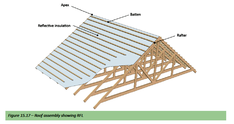
The most common method of installation in domestic applications is where the RFL is stapled with industrial staples to the top of the rafter (with timber trusses) before fixing of the batten or purlin. The insulation (RFL) material is then laid horizontally (gable to gable) commencing at the eaves an ensuring that subsequent sheets overlap the previous sheet by 100mm. With this method the RFL acts as both insulation and as a waterproofing membrane.See figure 15.17
A second layer of RFL (either sarking or foil batts) beneath the roof will increase resistance to radiant heat. This may be useful in hot climates. However, ensure that there is at least a 25mm gap between reflective surfaces.
Ceiling
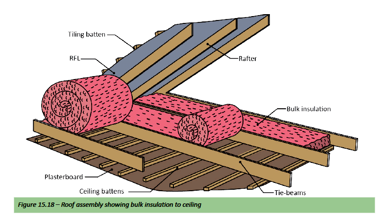
Place ceiling insulation between the joists. Suitable bulk insulation includes bulk batts, mats, cellulose loose fill and polystyrene boards. In colder climatic regions two layers of bulk insulation may be necessary to increase thermal performance, one between the rafters and the second on top. Other insulation types include flexible composite bulk and reflective materials which combine some features of both types; and can be installed in the same way as bulk insulation except that the reflective foil would determine its position i.e. facing downwards. See figure 15.18
Other suitable bulk insulation includes multi cell or concertina style batts and boards. These batts or boards can be friction fitted between rafters or on top of ceiling rafters. Placing the insulation between the tie-beams/rafters is preferable. Be extremely careful of electrical wiring in the ceiling. Where possible, place insulation under electrical wires and use a suitable spacer to lift wiring above insulation to allow a suitable air gap. Other safety precautions are required when installing insulation; clearances must be left to hot objects such as flues from fires, recessed light fittings and transformers. There are cautions related to covering ceiling tie-beams/ rafters with insulation. Safe places to walk are not identifiable when accessing the roof space. It is also recommended that one makes use of kneeling boards when installing ceiling insulation. Install insulation strictly in accordance with the manufacturer’s instructions.
Note: The National Building regulations Part XA (SANS10400XA) sets out minimum requirements for materials R-values for different climatic zones used in roof assemblies – refer Standards
Ceilings that follow the roof line
These include sloping ceilings, cathedral ceilings, vaulted ceilings, and flat or skillion roofs, where there is no accessible roof space.
Roof
A layer of reflective foil laminate (RFL) is an effective barrier to radiant heat and as a vapour barrier. Reflective insulation gives excellent insulation performance for downward heat flow (summer heat gain), but only moderate performance for upward or horizontal heat flow (slowing heat losses in winter) and requires an air space between the foil and solid surfaces to achieve full insulation qualities. RFLs should be installed in conjunction with conventional bulk insulation, to achieve optimum energy efficiency.
Place reflective foil insulation as follows (depending on product) with the shiny side facing down;
- Under steel sheeted roofs – (directly under the roofing material) over purlins or timber battens or straining wires as required, or
- Under tile or slate roofs – between the battens and the rafters i.e. under the timber batten, or
- In accordance with the manufacturer’s instructions
Foil backed or faced blankets (composite insulation) can also be used (although they are primarily designed for application where no ceilings exist) where the outer jacket reflects heat and controls condensation under steel sheeted, fibrous cement and tiled roofs (acting as a vapour barrier); and where the bulk insulation provides thermal and acoustic insulation mainly to reduce the noise associated with metal roofing. When used for thermal insulation, compression of the blanket over the battens or purlins lowers the total R-value.
Ceiling
- The first step lies in the design – ceilings that follow the roof line require enough space to accommodate adequate insulation, including any necessary air gaps and where:
- Ceilings with concealed rafters are easier to insulate and should be considered in preference to ceilings with exposed rafters, and
- Ceilings with exposed rafters require insulation products with a higher R-value per unit thickness due to space limitations within the ceiling.
Consult the insulation manufacturer or installer about installation clearances. As a rough guide, minimum clearances (batten height) for ceilings with exposed rafters are:
- Rval 2.88 Flexible fibre glass (glasswool) blanket: 115mm
- Rval 2.0 polystyrene boards: 65mm
Suitable composite insulation for exposed rafter applications includes foil faced polystyrene boards (it is a lot easier to install); the minimum batten height should be 65mm to allow for two 25mm reflective air spaces either side of the boards where 25mm boards are being used. 25mm foil faced polystyrene boards and RFL insulation will give a total R-value of approximately 1.7 up, 2.9 down.
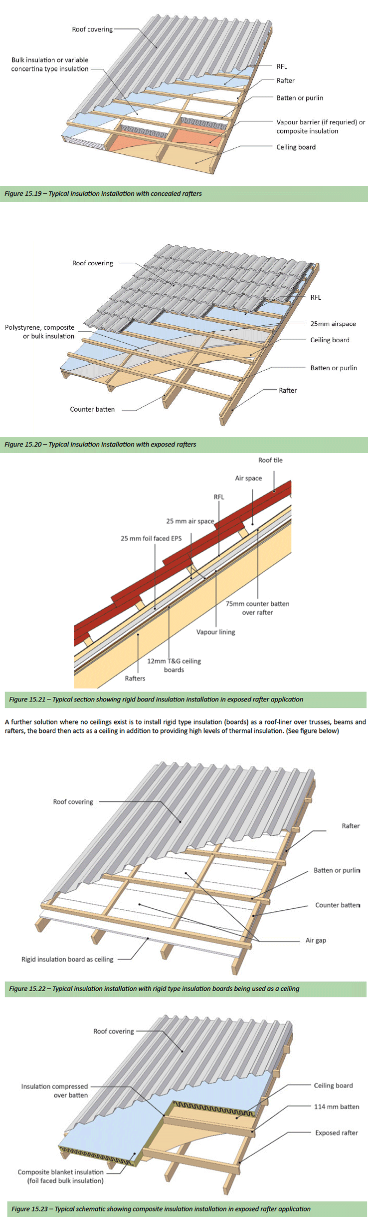
No Ceilings
In South Africa, many low cost homes and retail and industrial buildings are built with no ceilings, where as much as 70% of the heat gain is through the roof. The over purlin under roof sheet insulation is the most cost effective method of achieving thermal efficiency in these building types. A layer of reflective foil laminate (RFL) is an effective barrier to radiant heat and as a vapour barrier. Reflective insulation gives excellent insulation performance for downward heat flow (summer heat gain), but only moderate performance for upward or horizontal heat flow (slowing heat losses in winter) and requires an air space between the foil and solid surfaces to achieve full insulation qualities. RFLs should be installed in conjunction with conventional bulk insulation, to achieve optimum energy efficiency. Foil backed or faced flexible bulk blankets (composite bulk insulation) are primarily designed for applications where no ceilings exist and where the outer jacket reflects heat and controls condensation under steel sheeted, fibrous cement and tiled roofs (acting as a vapour barrier); and where the bulk insulation provides thermal and acoustic insulation mainly to reduce the noise associated with metal roofing. When used for thermal insulation, compression of the blanket over the battens or purlins lowers the total R-value. There are various application options available when installing the above two types of insulation (which can include applications where ceilings are installed) depending on the particular roofing material and or design, construction method and project requirements i.e. Insulation only; insulation and waterproofing membrane; ceiling substitution, noise etc.
Flexible reflective foil laminate insulation (RFL)
RFLs can either be laid horizontally i.e. in the same direction as the purlins or battens which is normal in domestic applications where the truss or rafter centres are usually less than 1500mm. While in industrial applications RFLs are laid vertically as the truss and rafter centres are usually greater than 1500mm, where the RFL is then laid vertically using straining wires. The most common domestic application of installing RFLs is illustrated in figure 15.17 – i.e. stapled with industrial staples to the top of the rafters before fixing the battens. Material is laid ‘horizontally’ (Gable to Gable) commencing at the eaves an ensuring that subsequent sheets overlap the previous sheet. With this application the RFL acts as both insulation and a waterproofing membrane. The RFL can also be laid and stapled ‘horizontally’ on top of timber rafters and battens or purlins before fixing of the roof covering (usually sheeting). See figure 15.24 on the following page.
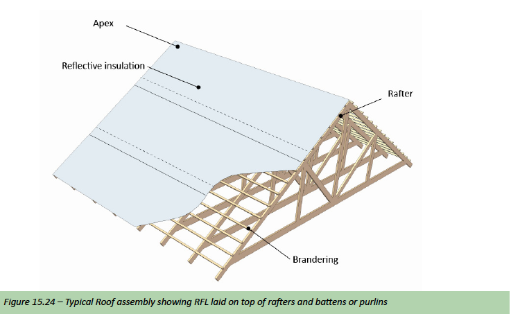
Composite bulk insulation
Composite bulk insulation can either be laid horizontally which is normal in domestic applications where the truss or rafter centres are usually less than 1500mm. While in industrial applications composite bulk insulation is laid vertically as the truss and rafter centres are usually greater than 1500mm, where the composite bulk insulation is then laid vertically using straining wires.
Only some composite bulk insulation products are recommended as water vapour barriers and if this is a requirement; this needs to be checked with the manufacturer, before specifying the product.
Composite bulk insulation in domestic applications can be installed in the following ways:
- Under tile or slate roofs under timber batten
- . Under steel roofs over purlins or timber battens
- . above ceiling laid loosely in roof space
- above ceiling installed between timber battens and roof trusses
See schematic – Figure 15.25.
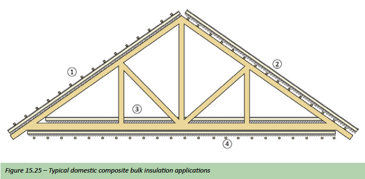
The most common domestic method of installation is where the blanket is installed as (2) above; where the insulation (the fibre side facing upwards) is stapled with industrial staples to the top of the rafter or truss before the fixing of the batten.
Material is laid ‘horizontally’ i.e. in the same direction as the battens, commencing at the eaves an ensuring that subsequent sheets overlap the previous sheet with the edge without the loose lap laid over the lap of the previous sheet, depending on product and manufacturer.
When installed horizontally the blanket needs to be fixed firmly so as to prevent sagging.
When used for thermal insulation, compression of the blanket over the battens or purlins as per fixing details 1, 2 & 4 as described above, the total R value of the blanket is lowered.
In sheeted roof applications, fix the roof sheeting as soon as possible after the fitting of composite bulk insulation using the specially designed roofing screws normally recommended by the manufacturer of the product. Care should be taken to ensure that weight is applied to the drilling point to facilitate drilling without distortion of the composite bulk fibre. Where the roofing is in sheet form and with trusses spaced at greater than 1500mm centres the industrial method of installation is normally used with straining wires – See Figure 15.26.
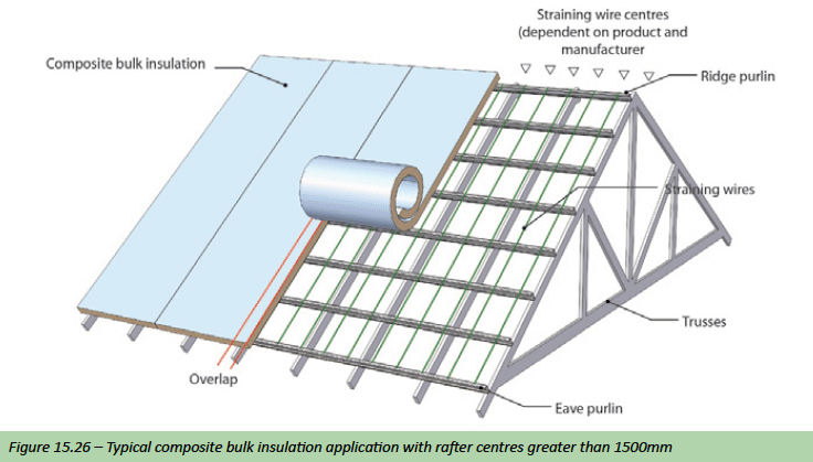
Insulation tips
Moisture
The thermal insulation values of materials reduce with increased moisture content so that materials which do not absorb water are needed where prolonged wetting e.g. through condensation is inevitable. Some thermal insulation materials are more vulnerable than others; for example cellulose.
Thermal Bridges
The overall insulation value of a roof assembly can be degraded by thermal bridges where high thermal transmission material penetrates layers of low thermal transmission material. Thermal losses due to cold bridges are often ignored in calculations, especially where thin sections are involved; but these and other materials such as steel roof trusses or steel beams become more important in the overall R-Values of the roofing assembly in terms of the “deemed-to-satisfy” requirements of the standard.
Some cold bridges are also important because they produce inside surface temperatures below the dewpoint of the air, leading to selective condensation on parts, for instance, of a ceiling. Suitable designs can overcome or reduce cold bridging to acceptable levels. Air movement into and within the roof space, and especially through layers of low density insulation material, can reduce thermal efficiency considerably. Sealing at joints and around areas where services penetrate the insulation is important.
Condensation
Condensation occurs on a surface when its temperature falls below the dew point of the air for a sustained period. In these conditions, the relative humidity of the air in direct contact with the cold surface rises to 100% and the moisture in the air condenses on the surface.
On a clear night, the outer roof covering radiates heat to the sky and its temperature may fall even below that of the surrounding air. If the relative humidity of the air inside the building is greater than about 60%, there may then be a risk of condensation on the underside of the roof unless precautions are taken to avoid it; the risk is especially high in profiled sheet roofs.
Interstitial condensation occurs out of sight within the thickness of a roof or other part of the building structure when water vapour diffuses through the internal fabric, including any insulation, and condenses on a cold surface beyond. Interstitial condensation can rot and or weaken roofing components especially timber and can lead to deterioration in other organic materials; it can also corrode metal and other components.
There are three main ways in which the risk of condensation in roofs can be reduced:
- Installing thermal insulation in the roof assembly to reduce heat losses
- Installing a vapour control layer on the warm side of thermal insulation to restrict moisture which diffuses through the insulation from condensing on any colder outer surface
- ensuring cross-ventilation of the roof space to remove excessive moisture, more especially in regions with high humidity, for example climatic zone 5
Shading
Outline
With today’s development of window and glazing systems with low U-values and low energy losses, it makes it possible for large glazed surfaces to be used in buildings. However, large glazed surfaces need solar protection or shading, since otherwise there is a risk of overheating in summer and noncompliance in terms of the National Building Regulations – Part XA. The term shading refers here to the roof overhang or any shading device like awnings, pergolas, horizontal slatted baffles (aluminium louvres), roller blinds, venetian blinds, shutters, etc. Some shading devices can also act as overnight insulation for windows, like roller blinds or shutters.
During the design phase it is recommended to assess the comfort and energy required for heating or cooling, if the building is to function properly. However, shading and/ or shading devices are seldom designed during the design phase and are typically installed as an afterthought when problems are encountered, i.e. after the first summer that the building has been in use. Although with the proper implementation of SANS 10400 XA many of these problems should be avoided – see the sub section on standards that follows after shading guidelines.
Shading Guidelines
In general it is best to block the sun before it reaches the window. However when choosing an appropriate shading device one must also consider whether a fixed device or moveable device will be better; as the need for protection will be seasonally dependent in its effects. For example, a roof overhang (eave) may block high summer sun while allowing through low-angle winter sun. (We use the term window which could include a door (glass) or an opening). Some form of adjustable or moveable shading device is usually the better option, as it provides the home owner some control over the effects of the shading device and especially where glare is of concern. There are a variety of shading strategies that are discussed below under shading guidelines.
Orientation
North-facing elevations (and south facing ones above the tropic of Capricorn) receive higher angle sun and therefore require narrower overhead shading devices than east or west facing openings; as the angle of incidence is greater, much of the radiation is reflected from the glass or blocked by the walls on either side of the window, especially if the window is fitted deep into the reveal. Fixed horizontal shading devices are often adequate above north facing windows, which could include eaves, awnings, and pergolas with beams spaced at correct centres or louvres set to the correct angle, to allow sufficient winter sun through.
East-facing elevations require a different approach, as low morning sun from these directions is normally most welcome in winter and in many cases also welcome in summer, but can become a problem in so far as glare is concerned and therefore more difficult to shade. This morning sun is not as intense as the afternoon west sun; however in certain coastal areas in South Africa especially in climatic Zone 5 this morning sun can be problematic, presenting overheating problems that would require the use of an appropriate shading device.
South-facing elevations don’t usually require any shading apart from certain locations like climatic Zone 4, where the afternoon summer sun sets very late and could present some glare.
West-facing elevations present the biggest problem with solar heat gain. This hot summer afternoon sun from these directions is quite intense, causing overheating, fading etc. and added to this, the challenge of screening glare with this direct low sun. The sun can be low enough in the sky that only a very wide overhang can be effective. Adjustable shading is the optimum solution for these elevations. Appropriate adjustable systems include sliding screens, louvre screens, shutters, retractable awnings and adjustable external blinds. Deep verandahs, balconies or pergolas can be used, but may still admit very low angle summer sun, where using trees in combination with other planting to filter unwanted sun can help solve this problem.
North-East and North-West elevations require an integrated approach as they receive a combination of high and low angle sun throughout the day. Adjustable shading devices are recommended for these elevations and it is further recommended to select systems which allow the user to exclude all sun in summer; choose full sun in winter; and manipulate sun levels at other times. Figure 15.27 shows the path of the sun in summer and winter in order to illustrate the impact of orientation on solar shading. As illustrated in this figure one can see that the sun is at its lowest in the sky on the winter solstice (21 June) and where shading is most likely to occur. Whilst in summer and at the summer solstice (21 December) the sun is at its highest where very little shading is likely to occur In the table that follows (Table 15.25) the angles of elevation of the sun over the horizon as seen by the observer at different cities in South Africa at different times of the day is illustrated.
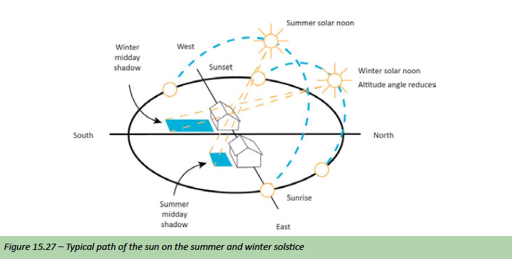
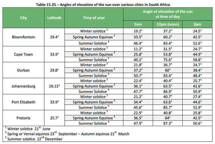
Guidelines for all climates
Use external shading devices wherever possible over openings, windows and doors; lighter-coloured shading devices reflect more heat. Internal shading will not prevent heat gain unless it is reflective. Use plants to shade the building, particularly windows, to reduce unwanted glare and heat gain. Evergreen plants are recommended for humid sub-tropical climates (Zone 5) and some hot and dry climates (Zone 3). For all other climates use deciduous vines or trees to the north, and deciduous or evergreen trees to the east and west. For latitudes north of 27.5°S the response varies with climate. For humid sub-tropical climates and hot and dry climates with no passive heating requirements, shade the whole building at all times. For hot and dry climates with passive heating requirements allow some low angle winter sun to reach walls, concrete floors and windows. The simplified climatic zone table below is for quick reference for the application of solar shading.
Fixed shading
Fixed shading devices (eaves, pergolas and louvres) can regulate solar access on northern elevations throughout the year, without requiring any user effort. Summer sun from the north is at a high angle and is easily excluded by fixed horizontal devices over openings. Winter sun from the north is at a lower angle and will penetrate beneath correctly designed fixed horizontal devices (see figure 15.27 – above). For locations north of the tropic of Capricorn (23.5°S) in high humid climates or hot dry climates with warm winters, the building and outdoor living spaces should generally be shaded throughout the year. Listed below are the more common types of fixed shading systems.
Eaves
Correctly designed eaves are generally the simplest and least expensive shading method for northern elevations, and are all that is required on most single storey houses. Having said that, permanently shaded glass at the top of the window can become problematic if not designed correctly as it is a significant source of heat loss, especially in temperate and cold climates (Zone 1 & 2). To avoid this, distances between the top of glazing and the eave underside (G) needs to be calculated correctly (See Figure 15.28 – Method of measuring P and H) this calculation is further dependent on latitude and the extent of summer shading required.
However, this calculation is often not as simple as it seems, as the National Building Regulations have a prescribed minimum roof height of 2.400m, with a normal window head height set at 2.100m. This renders the above solution then almost unworkable; with the only solution being to increase the window head to eave distance i.e. to raise the roof height which will increase costs.
Awnings and pergolas
Awnings and pergolas need to extend beyond the width of the opening by the same distance as their outward projection. Pergolas covered with deciduous vines provide self-adjusting seasonal shading.
Louvres
Fixed horizontal louvres set to the noon midwinter sun angle and spaced correctly allow winter heating and summer shading in locations with cooler winters. Midwinter and midsummer noon sun angles for locations (x) can be calculated using the formulas below, where (L) is the latitude of your home.
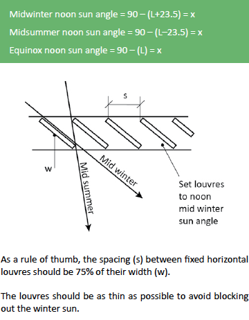
Adjustable shading
Adjustable shading allows the user to choose the desired level of shade while enabling daylight levels and maximizing views. This is particularly useful in spring and autumn when heating and cooling needs are variable. External adjustable shading systems appropriate for northern elevations include retractable awnings or horizontal and facade louvre systems, while removable shade cloth over pergolas offers a flexible and low cost shading solution. Other external adjustable systems include sliding screens, louvre screens and shutters. Controllable louvre systems with controllable fins mounted vertically in front of windows or fitted horizontally above a window, reduce the likelihood of ‘overshading’ or ‘undershading’ that frequently happens with fixed shading devices and will result in the optimum shading angle all year round.
Using plants for shading
Match plant characteristics (such as foliage density, canopy height and spread) to shading requirements. Choose local indigenous species with low water requirements wherever possible. In addition to providing shade, plants can assist cooling by transpiration. Plants also enhance the visual environment and create pleasant filtered light.
- Deciduous plants allow winter sun through and exclude summer sun.
- Trees with high canopies are useful for shading roofs and large portions of the building structure.
- Shrubs are appropriate for more localised shading of windows.
- Wall vines and ground cover insulate against summer heat and reduce reflected radiation.
- Use drought tolerant ground-cover plants instead of paving where possible, to keep the temperature of the ground and surrounding surfaces lower in summer.
Standards
Extracts from SANS 204
- 4.4.5 Shading
-
4.4.5.1 Where shading is required, the building shall
- a) Have a permanent feature such as a veranda, balcony, fixed canopy, eaves or shading hood, which
- Extends horizontally on both sides of the glazing for the same projection distance P in figure 15.28, or
- Provides the equivalent shading with a reveal or other shading element – see figure 15.29,
- b) Have an external shading device, such as a shutter,
blind, vertical or horizontal building screen with
blades, battens or slats, which- Is capable of restricting at least 80 % of summer solar radiation, and
- If adjustable, is readily operated either manually, mechanically or electronically by the building occupants.
- a) Have a permanent feature such as a veranda, balcony, fixed canopy, eaves or shading hood, which
- 4.4.5.2 For glazing where G exceeds 0,5 m, the value of P as
shown in figure 15.28 shall be halved.
Note: An adjustable device that is capable of completely covering the glazing may be considered to achieve a P/H value of 2.
-
4.4.5.1 Where shading is required, the building shall
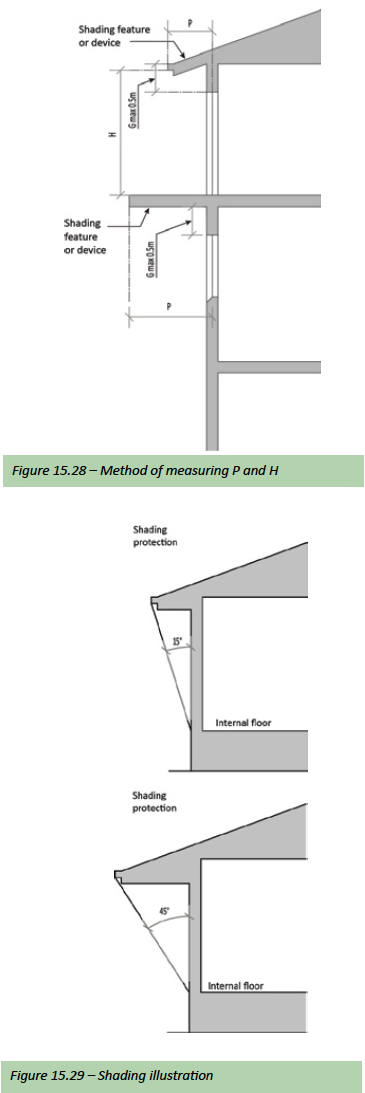
Roofing Accessories
Outline
Roofing accessories are the items other than the roof covering that can or should be used to complete the roofing installation; for example, installing a facia board at the eaves or a metal flashing to a parapet wall.
Note: In this book we cover or illustrate the two main different roof coverings being tile or sheeted; although many roofing systems have a number of different and special application accessories they are too broad to try and discuss here in detail.
Ridge tiles and verge tiles
The ridge is the horizontal junction between two roof slopes at the apex. Ridges should be covered with ridges or ridge tiles of similar colour and finish to those of the roof covering and in the case of ridge tiles they should be edge-bedded onto the last course of tiles in tinted 3:1 sand/cement mortar, strictly in accordance with the manufacturer’s recommendations. All ridge tiles should overlap the last course of tiling by a minimum of 75mm and the exposed mortar must be neatly pointed.
A strip of approved DPC sheeting 150mm wide should be placed lengthwise under the ridge tiles, overlapping the top course of tiling on each side by 25mm. Lapped ends must be supported underneath and the overlap should not be less than 150mm. The end ridge tiles at gable ends should be solid bedded with mortar inset with pieces of tiles and neatly pointed
at fair ends. All ridge tiles shall be neatly cut and mitred at intersections with hips, intersecting ridges etc.
In the case of sheeted roofing applications – see the following sub-section – Flashings – Ridging. All ridges do however need to be installed and fixed in strict accordance with the manufacture’s recommendations. Monoridges are to be formed with purpose made monoridge tiles edge-bedded onto the top course of tiling as described for ridge tiles strictly in accordance with the manufacturer’s recommendations.
The Verge of a roof can be described as the edge of a roof surface at a gable. And unless otherwise specified, verges should be formed with purpose made verge tiles of similar colour and finish to those of the main roof covering and must be fixed strictly in accordance with the manufacturer’s recommendations. In sheeted roof applications where the roof is installed between parapets flashings would need to be installed – See flashings in the following sub-section.
Hips
Hips are covered with ridge tiles/hip tiles of similar colour and finish to those of the main roof tiles and usually the same as the ridge tiles. In the case of sheeted roofing applications the hip is usually the same profile to that used as described above under ridges. For tiled roofs the hip tiles should be cut closely to the rake of the hip, and the hip tiles should be edge-bedded onto the tiles as described for ridge tiles.
The first hip tile should be shaped at the foot to the line of tiling at the eaves and the fair end filled with mortar inset with pieces of tile and neatly pointed. Alternatively hip starters can be used – most manufactures do supply hip starters. For vertical hips and at steep pitches above 45°, hip irons should be used and fixed to the hip tree with two screws or nails to support the first hip tile. All other hip tiles must be nailed to the hip tree and bedded as detailed for hips and ridges.
Fascia and barge boards
They provide a functional finish by protecting the underlying exposed timber structure from the elements at roof ends, as well as adding visual impact to the building. In high wind areas barge boards form an important component of the roof structure, as they protect slates or tiles from being dislodged by the wind at the gable ends.
A Fascia Board; is a trim set on edge along the eaves, to cover the rafter ends and can also carry the gutter or can also be described as the flat horizontal surface immediately below the edge of a roof. A Barge Board; is a sloping roof trim fixed in lengths along the edge of a gable to cover the exposed timbers or as some describes as an ornamental board along the gable end of a roof.
To ensure a high standard of finish, it is essential that the supporting timber structure is accurate. Warped, twisted or poor quality timber work will reflect in the final appearance of fascia’s and barge boards. Fascia and Barge boards are available in different types of materials, sizes and shapes. With fibre cement products being the most popular.
Gutters
A gutter can be described as a gently sloping channel to collect water and lead it to an outlet or drain. Roof gutters are no different and it is not always appreciated that gutters and downpipes form a system; roof gutters can be described in four specific functions:
- Can run along the eave to collect the water
- Down a valley to drain water
- Behind a parapet or chimney to direct water
- Where one or two inverted roofs meet to drain and direct water
Many systems that have adequately sized gutters and downpipes fail in their function because of incorrect falls, insufficient downpipes or incorrect outlet locations, incorrectly installed box gutters or conditions at the outlets causing water to back up and spillover.
A roof guttering system serves three basic purposes:
- They form an aesthetically pleasing look to a roof line (create a band).
- To keep the curtain of rain water from drenching one when trying to enter or exit a building
- Most importantly they protect the foundations and plinths of buildings from subsidence, rising damp and the associated
damage caused by the splash back onto the walls.
Sizing of gutters and downpipes for domestic installations has become relatively straightforward, although the design of such systems for larger buildings is rather more than a simple calculation of roof area and water load.
The rainfall pattern over most of South Africa is variable in the extreme, so that even in so called dry areas, high intensity rainfall of short duration can be experienced. It is the intensity of rainfall, rather than the total amount, which is the important factor in designing roof drainage for roofs and paved areas.
Gutter capacity
The flow capacity of a gutter will vary according to the fall of the gutter and the positioning of downpipes and gutter angles, e.g. an outlet situated centrally in a length of gutter drains water from the gutter at twice the rate provided by a single end outlet. See size selection table below.
Gutter fall
Tests show that the performance of eaves gutters is improved by 20% at a fall of 1 in 600. Excessive falls on the other hand should be avoided because, apart from the bad appearance, a wide gap between the roof edge and the gutter results in wind driven rain water missing the gutter altogether. The presentation of data relating to the flow capacities of gutters varies considerably from simple tables to the more complex. In many cases the architect , building contractor or whoever installs the gutters has the task of deciding exactly what to use, and becomes quite confused and relies in the end on instinct. In general a feeling of distrust prevails where on the one hand the design data is too brief, or at the other extreme, the thesis outlining the principles of design is too academic and complex. And in many instances the cost is the ultimate deciding factor even if it means the installation of a guttering system is at risk of functional failure.
Determining the Sizes of Gutters
Downpipes Size Selection Chart
Downpipes Size Selection Chart
The chart given below has been based on the assumption that 10cm² of gutter and 8cm² of downpipe is sufficient to effectively drain 10m² of roof area under average rainfall conditions. To calculate for heavy rainfall conditions, however, sizes should be based on a figure of 10cm² of gutter and 8 cm² of downpipe for 7m² of roof area. Conversely, if dry conditions prevail, calculations should be based on 10cm² of gutter and 8cm² of downpipe being sufficient for 14m² of roof area. If, therefore, gutter sizes are required for a roof under these rainfall conditions, the measured area of the roof may be increased by 43% for heavy rainfall conditions or reduced by 28% for dry conditions and the gutter and downpipe areas required read off the chart as for normal conditions. Example: Roof Area 150m² Gutters 150cm² use either 200mm half round gutter or 150 x 125 x 150 VHV (square) gutter. Downpipes 120cm² use 100mm round downpipes.
If required consult your local authority for rainfall conditions in your area to determine your gutter requirements or the SA weather services. www.weathersa.co.za www.southafricanweather.co.za
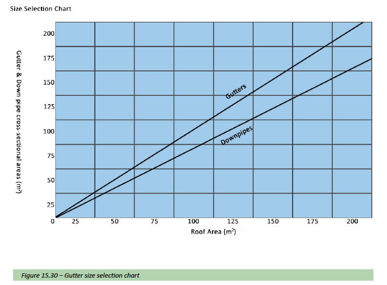
Flashings
Outline
It is good roofing practice that all exposed terminations and abutments are either flashed or counter flashed. A variety of flashing methods and systems are available. The nature of the roof covering and vertical surface including aesthetic requirements will determine the flashing type. Flashings at a roof/wall abutment may be in two parts, with an up-stand flashing turned up the wall and a counter flashing turned down over it.
Flashing material types
Metal flashing
Generally consisting of either galvanised sheet, copper or lead in various shapes and forms; these flashings are of a permanent nature and are installed by a plumber or roofer.
Bitumen flashing
This is one of the most commonly used and effective flashing methods, used in flat roof applications. The asphalt is a trowelable mixture of solvent-based bitumen, mineral stabilizers, other fibres and or fillers. Fibreglass or other fibre reinforcing is sandwiched between two coats of asphalt cement, applied by trowel or brush over the terminating edge of the felt and sealed to the wall. The flashing compound may be blended with fine sand to ensure a key for subsequent painted finish. The terminating edge of the felt is trimmed to ensure a smooth, neat and effective finish.
Fibre reinforced acrylic flashing
Similar to bitumen flashing above but incorporating liquid acrylic, commonly referred to as ‘Flash Harry’. This provides an aesthetic finish and may extend to the top of the wall/ parapet. If applied as intended this product can assist in waterproofing roof transitions and parapets effectively and in difficult places, however this product is so often used in applications that are not fit for purpose, resulting in a number of failures.
Cementitious flashing
A resin bonded cement reinforced with a polypropylene fabric provides reasonable adherence to brickwork or plastered vertical surfaces and provides a tough finish that may be plastered, tiled or painted; however not recommended for use at transitions between different materials.
Note: No nails should pass through any part of a flashing.
Formed flashing types
Formed flashings are available from various different manufacturers; all manufactured with the same fundamental shapes as described below, and made for the following purposes.
Ridging
The purpose of ridging is to effectively seal the ridge of a dual pitch roof using sheeting as a covering.
- Rolltop ridging is manufactured to be used on corrugated iron roofs. The significant roll in the centre of the ridging aesthetically matches the profile of the corrugated iron.
- IBR ridging is manufactured to be used on an IBR roof or where IBR roof sheeting has been used for cladding. The significant sharp profile matches the aesthetic look of IBR roof sheeting.
Cover flashing
Is used to effectively seal a roof against a wall and is fitted over the overtile or undertile flashing depending on the detail required and roof covering.
Overtile flashing
Is used where a roof abuts against a parapet wall (sidewall or headwall); and needs to be effectively sealed. This type of flashing is mainly used on roofs with metal sheeting as a covering. The flashing is visible after installation.
Undertile flashing
Is used mainly to seal the roof where the roof abuts against a parapet wall (side wall).This type of flashing is installed against the side wall and fits underneath the roof covering – typically concrete roof tiles; the short lip hooks underneath the tile to secure the flashing.
Valley flashing
Is used in the valley of a roof where two roof planes join together. It usually has 225mm on either side of the bend with a short lip on both sides to prevent water running off the flashing. Valley flashing is manufactured in one size only.
Note: Roll top ridging is also known to be used as a valley lining, provided the ends are bent over creating a lip.
Valleys for tiled roofs
For open valleys the adjacent tiling must be neatly cut on both sides to form an open channel of at least 100mm wide. The cut tiles must be well fixed to the battens. For closed valleys the adjacent tiles must be neatly cut on both sides to form a close fit and a straight line. The tiles must be holed and secured by nailing. If the cut tiles are very small and cannot be nailed they must be secured to the battens by means of bailing wire.
Waterproofing
Outline
Waterproofing tends to be one of the trades that are mostly overlooked when building, not only in the design phase, but throughout the building process resulting in a number of failures directly attributed to poor or incorrect waterproofing detail, and (or) the incorrect choice of materials or system being used (not fit for the purpose intended). Added to these; poor workmanship and the use of inferior products, in order to save money just make matters worse.
Trying to save money on waterproofing a roofing slab is very short sighted, considering the cost vs. the performance criteria of incorrect or inferior waterproofing systems/ products or poor workmanship or lack of detail after the building is complete, is very costly and in some instances impossible, unless one literally starts all over again. Waterproofing has advanced tremendously in recent years, from membranes, coatings and systems. Leaving the contactor or home owner with many different options available, ensuring a roofing slab is completed free of waterproofing defects and the ingress of water. If you are unsure of what system would best suit your specific application, consult with your architect or structural engineer or a reputable waterproofing contractor or manufacturer for advice.
Waterproofing can be used in a number of different applications, which include vertical and horizontal surfaces:
- Waterproofing of basements and other structures underground
- Parapets, kerbs and flashings
- Planters
- Concrete floor slabs
- Suspended slabs
- Boarded and flat Roofs
Although in this section we only describe roofing slab applications and therefore only horizontal surfaces.
Roofing slab waterproofing basics
In the design, choice and specification of any roofing slab waterproofing system, the following basic principles and questions must be considered.
- Get the water off the membrane – We are not building dams; always create sufficient falls and cross falls before applying any type of waterproofing system to a roofing slab or balcony
- Substrate – As in the case of painting it is equally important with waterproofing that the substrate be stable and smooth.
- The waterproofing system is not a structural element of the building – Waterproofing membranes are not designed to keep the structure together in the case of cracking. Special design and attention must be given to movement and expansion joints.
- Have sufficient water outlets (downpipes) been installed to remove the rainwater from the area of roofing slab and have they been installed correctly and to specification and does the slab fall to these points.
- Have emergency outlets been provided for in case the outlets get blocked or flooding occurs.
- Workmanship – Waterproofing manufacturers do not knowingly produce products that are not waterproof. The products might have different live spans but in many cases, the human factor plays the biggest part in failures of waterproofing systems. You can use the best product on the market but if applied incorrectly, it will fail.
The following questions need to be answered before choosing a waterproofing system.
- What goes on top? – The required final finish including the aesthetic appearance and functionality must be considered before the choice of waterproofing system can be made.
- What goes underneath?
- What needs to be protected?
Membranes
Membrane waterproofing systems whether torch-on, acrylic or other, are the only certain method of waterproofing roof slabs. Systems are essential in a variety of applications, as they provide durability, dimensional stability at different temperatures (thermal movement) and most are installed with a guarantee. Manufacturers also provide assistance from specification support at design phase to on-site support during material/system application.
Torch-on Membranes
Torch-on membranes can be described as sheets of fibres matted into felt and bonded by saturating with bitumen, bitumen-polymer or other modified bitumen’s and other components such as rot-proof polyester reinforcements. The fibres are usually a non-woven polyester fleece, or glass wool, which both have better resistance to puncturing or tearing. They are mostly applied by torching-on and can be used in dry applications like roofing and damp proof membranes. Torch-on systems are generally the most suitable and the most commonly specified waterproofing systems used for concrete roofs. Torch-on systems are basically bitumen felt sheets welded together to create a waterproofing membrane to a concrete substrate, that has been primed using a bituminous solution with petroleum solvents.
Specifications
4mm membranes are the most commonly used, with the ideal system being; a double layer system which incorporates the application of two torch-on membranes; the under layer being a 3mm membrane and the top layer a 4mm membrane, which are typically used in roofing and balcony applications. There is a proliferation of membranes being imported into South Africa. With some not suitable for use in our climate and are only suitable to use as a “cap sheet” or top layer.
Covered grade membranes (CG) are typically available in the following thicknesses.
- 2mm (1.7mm) membranes are used as a multipurpose underlay and DPC.
- 3mm as a torch applied membrane for buried situations.
- 4mm as a torch applied membrane for underground tanking, parking decks, retaining walls, roof gardens etc.
Exposed grade membranes are a range of superior quality special polyester (SP) dual reinforced membranes to suit exposed applications and available in the following thicknesses.
- 3mm as a torch applied membrane for box gutters, parapets and as an underlay to a dual system using a 4mm top sheet.
- 4mm as a torch applied membrane for flat roofs, boarded roofs, parking decks, balconies, terraces, reservoirs etc.
Applications
Concrete/screeded Roofs (Slabs)
Concrete/screeded Roofs (Slabs)
This application refers to general low-slope (less than 5° pitch) concrete roofs screeded to falls and cross falls to rainwater outlets where the roofing membrane is exposed to the elements and temperature fluctuations. The waterproofing membrane, correctly selected, installed and maintained, is now considered as a permanent structural element with a life expectancy equal to that of the building it is protecting. Simplicity in design together with proper preparation of the substrate are key to successful roofing.
Substrates
As with most membranes and coatings, the substrate plays an extremely important part in the success or failure of the waterproofing system. Too often Waterproofing Contractors do or are compelled to install the waterproofing system on inadequate or poorly prepared surfaces.
Falls and Drainage
It is generally accepted that low-slope (flat) roofs should have positive drainage. A finished fall of 1:80 is generally acknowledged as the minimum to ensure adequate rainwater runoff. To achieve this minimum finished fall, the roof should be designed with a fall of 1:60 allowing for directional changes and constructional inaccuracies. It is good practice to ensure that ponding of rainwater does not occur. Whilst most membranes are unaffected by standing water, it should be noted that ponding, besides being unsightly, could result in rapid deterioration of the final painted finish.
There are circumstances where the falls may be as low as 1:100 such as where the roof slope is in a single direction and great care has been taken to ensure there are no undulations in the screed. If no drainage falls and cross falls exist (not recommended) a duel layer system must be used.
Paint
- Bituminous Aluminium Paint – is the most widely used protective coating. Whilst not the most aesthetically pleasing finish it has particular advantages. Being bitumen-based, adhesion is assured and excellent solar reflection is achieved.
- Acrylic co-polymer Paint – available in selected colours and where waterproofing contractors must be advised by the paint manufacturer about the application procedure and suitability as regards adhesion to the flexible waterproofing membrane.
Crushed stone
A layer of light coloured stone chips laid loose over the waterproofing membrane provides a number of advantages:
- Insulation – the stone layer reduces diurnal temperature fluctuations
- Provides an aesthetically attractive finish
- Acts as a ballast – in high wind areas and for loose laid systems especially over insulation boards
- Ensures low maintenance costs
- Provides Ultra violet protection – extended material life
- Additional protection from hail damage
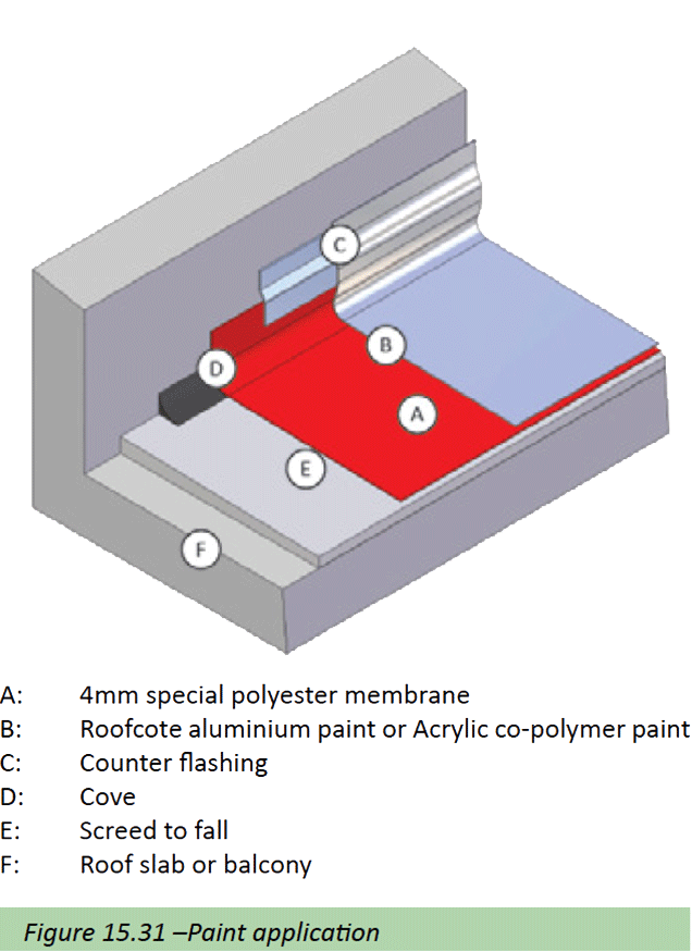
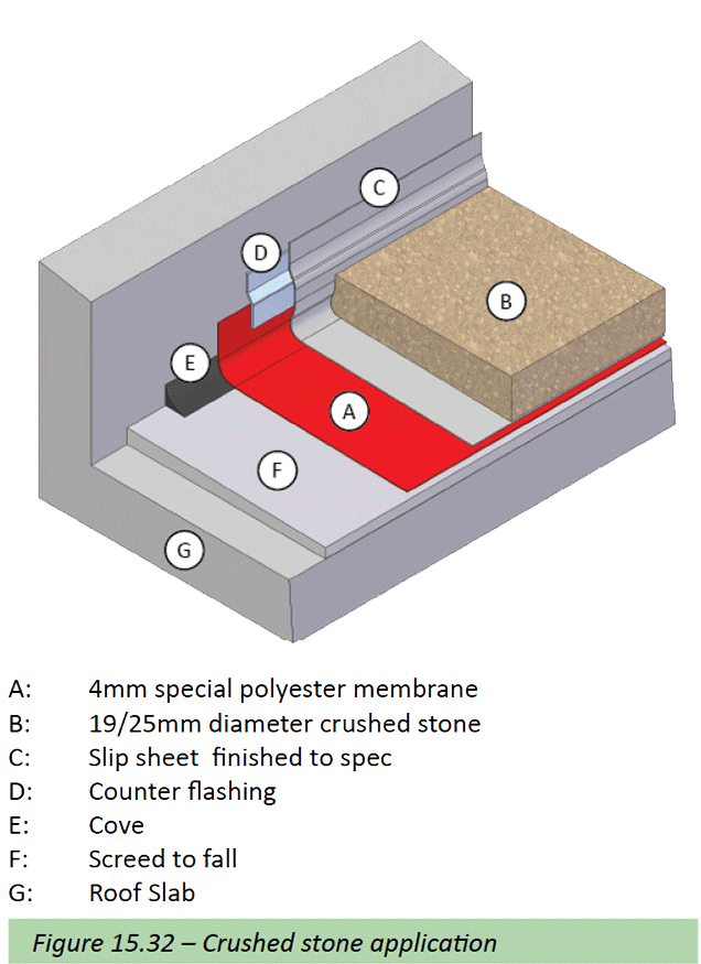
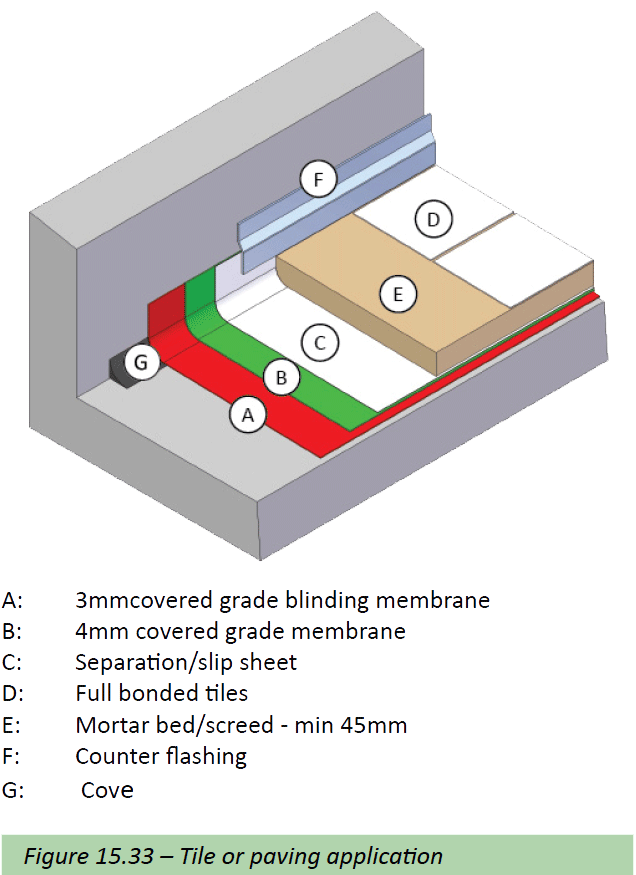
The crushed stone covering should be clean washed 19- 25mm in size and usually 50mm to 75mm deep. A stone-guard or band of larger stones should be positioned around the outlets so as to ensure that the smaller stone is not ‘washed’ down the outlets. It is considered good practice to apply a coating of bituminous aluminium paint on the waterproofing prior to laying the stone protection.
Balconies, terraces and patios
This application typifies pedestrian-trafficable areas such as balconies, patios and terraces under fully bonded tiles or pavers. These areas present some of the most difficult situations from a waterproofing point of view insomuch as there are often myriad complexities in usually confined areas. The cost of the waterproofing is often but a fraction of the cost of the finishes – consider the cost/risk ratio and give high priority to the design, surface preparation and installation. Most waterproofing contractors recommend the use of a dual-layer waterproofing system to obviate the risk of labour error and reduce the possibility of subsequent damage.
Isolation Layer/Separation sheet
Tiles or Pavers bedded in mortar are to be laid on an isolating membrane, such as Interdek or a PVC sheeting, so as to reduce stresses placed on the waterproofing by possible movement in the paved finish. This further will facilitate future removal and replacement of the tiled finish (if required). Movement joints (soft joints) between the tiles/pavers are to be created at approximately 3 metre centers and at all abutments.
In small areas (less than 10m²) the waterproofing may be installed directly to the concrete and the fall created in the mortar bedding without the use of an isolating layer. In such cases, the membrane is to be blinded with course sand in an emulsion binder. This will act as a key for the mortar bed. It is recommended that the minimum thickness of the mortar bed be 45mm.
Thresholds
The height of the door threshold is of paramount importance in that it will be determined by the thickness of the membrane, the mortar bedding and the tiles and also the necessary drainage falls. The minimum height of the waterproofing turn-up should be 100mm. The finished height of the waterproofing (turn-up) is to be higher than the finished paving surface. This is to ensure that surface water does not penetrate behind the skirting. Special precautions are to be taken so that wind-driven rain is prevented from entering the interior. Door and window frame fixing methods require careful detailing and should be done in consultation with the frame manufacturer. Too often, the frame is fixed mechanically through the waterproofing membrane.
Roof Erection
Outline
In South Africa, under the National Building Regulations, there are only two legal methods by which to design and construct timber roofs:
- Roof trusses manufactured in accordance with Part L Roofs of SANS 10400 “The Application of the National Building Regulations”. This standard outlines the ‘deemed to satisfy’ requirements for nailed and bolted trusses – See Standards page 8.
- The second method is to engage the services of a professional engineer (as required in part B of the National Building Regulations) who would work strictly in accordance with SANS 10160 Loading Code and SANS 10163 “The Structural Use of Timber.”
Tacit approval has been given by local authorities in general to pre-fabricated truss fabricators who use a suite of design programs supplied by system suppliers to design roofs up to 10m in span for non-public buildings.
Most of these system suppliers have been accredited by the Institute for Timber Construction. Larger buildings and those to whom the public has access are designed under the supervision of professional engineers using the same design programs.
Trusses designed by a competent person in accordance with Part B of the National Building Regulation are not limited to the span, pitch and geometric configuration of trusses specified in Part L of SANS 10400.
The Institute for Timber Construction works closely with both the Timber Division and the Civil Engineering Division of the SABS on grading specifications and design codes for structural timber as well as on matters affecting the National Building Regulations and the application thereof.
The Institute for Timber Construction have instituted a Certificate of Competence scheme for timber truss fabricators who design, manufacture and supply prefabricated nail-plated trusses.
Stringent auditing of the truss fabricators’ operations and key personnel before awarding these certificates is an assurance of quality trusses for specifiers and for the general public. The accuracy and performance of prefabricated timber trusses exceeds that of bolted trusses and cost savings are often significant.
Truss specification
Timber
All timber used for the construction of roof trusses, Rafters and beams should be structural SA pine complying with the requirements of SANS 1783-2/1460/10149, and bear the full standardisation mark. Timber used for roof battens should comply with SANS 1783-4 and bear the full standardisation mark. Timber used for the construction of roofs on site must be ordered in the dimensions in which it be used and must not be resawn into smaller cross-sectional sizes on site, as this will cause the grade, strength and dimensional tolerances to change.
Refer Roof Construction – Roof trusses – Timber Trusses
Timber treatment
In certain regions in South Africa, it is illegal to use timber for structural purposes, which has not been treated against biological attack. Treatment can be either with CCA or Boron in accordance with SANS 10005 “Treatment of timber.”
Understanding Wood Preservation
The South African Wood Preservers Association, discusses the basics of preservative treated timber and or wood and the subject of wood preservation. Wood preservation can be categorised into two types; primary (industrial) and secondary (DIY). Primary wood preservation involves an industrial process whereby wood is impregnated with an industrial biocide-containing wood preservative to render the timber durable and resistant to biological attack, i.e. decay fungi, and wood destroying insects such as wood borers and termites. The high pressure processes, involving the application of waterborne preservatives such as CCA and Creosote by means of vacuum and pressure cycles in autoclaves, are predominantly used. Other approved methods of primary wood preservation include immersion methods such as the hot and cold open tank process using Creosote; diffusion methods using Borates; and low pressure or double vacuum processes using light organic solvent preservatives (LOSP) such as TBTN-P or Azole Permethrin. Visit goo.gl/qWeHZ9 for an animation of the high pressure process used.
Primary wood preservation is a pre-treatment whereby the timber is treated prior to its intended end use application, and therefore is regarded as a preventative measure. It is not supplemental or remedial (after the fact). Chemical retention (take up), depth of penetration and the processes used are prescribed in SANS standards, and mandatory compliance is controlled through regulations and compulsory specifications, wherein compulsory third party product certification is specified.
Secondary wood preservation comprises the hand application of supplemental or remedial preservatives that contain active ingredients (biocides). These preservatives use mainly solvents as carrier and in some cases form part of protective wood finishes, i.e. wood sealers, and therefore used as a dual purpose supplemental or remedial preservative against biological attack as well as a protective finish against weathering factors such as UV, precipitation and temperature changes etc. Supplemental or remedial preservatives are mainly applied as a corrective measure to stop existing biological attack in untreated timber already in use, but can also be both corrective and preventative, i.e. treating exposed ends of pre-treated timber that has been modified or cut. Bandages, pastes and rods (sticks) with diffusible borate as the active ingredient also fall under the remedial preservatives, which are also used to augment and maintain primary treated timber exposed to high risk environments.
Supplemental or remedial preservatives usually require periodic maintenance to remain effective. Protective wood penetrating finishes and sealers that are applied by hand, i.e. by brush, paint, and spray, but which contain no active ingredients (biocides) are not regarded as preservatives but merely wood protective finishes, and as already eluded to, these type of products protect against weathering factors only.
Its application is however crucial when exposed timber (including preservative treated timber) is required to retain its natural wood luster and not acquire the grey to silvery weathered look.
Why preserve timber?
The natural durability of our commercially grown and used plantation species like Pinus and Eucalyptus, is low, rendering it susceptible to insect and fungal attack; therefore it is imperative to preserve the timber. Timber preservation also enhances durability and confidence in using timber and extends the life of timber, as well as providing the added benefit of increasing the carbon sink. Preservation of timber and the sale and use of preservative treated timber are regulated in South Africa. Regulation A13 1(b) in SANS 10400-A, as well sections in the NHBRC home builder’s manual, requires the use of primary preservative treated timber when used in a permanent structures in specific areas of South Africa. In addition compulsory specifications i.e. VC 9092 regulated by the National Regulator for Compulsory Specifications (NRCS) control the sale of preservative treated timber. All of the aforementioned regulations refer to SANS10005, The preservative treatment of timber, which specifies exactly in which specified areas the use of primary treated softwoods and hardwoods are compulsory.
Choosing the correct treated timber
SANS 10005 and the SANS product standards for preservative treated sawn timber (SANS 1288) and poles (SANS 457-2 or SANS 457-3) specify a Hazard Class system (H Classes), which categorises treated timber into different end-use applications based on the following:
- Different exposure conditions
- Potential risk of biological attack
- Preservative retentions/chemical loading
Product use information
Be sure to specify and use the correct H class timber for your intended application. Apply remedial preservative to all cross-cut and exposed areas. Under no circumstances must cross cut areas be exposed to ground contact unless retreated by pressure impregnation. Ensure that when poles THE HOW TO OF BUILDING 442 or posts are planted that in the ground that it is done in such a way as to allow for drainage of moisture or water taken up by the timber (see below).
How to plant a pole
The diagrams do not relate to structural details. Please consult a structural engineer.
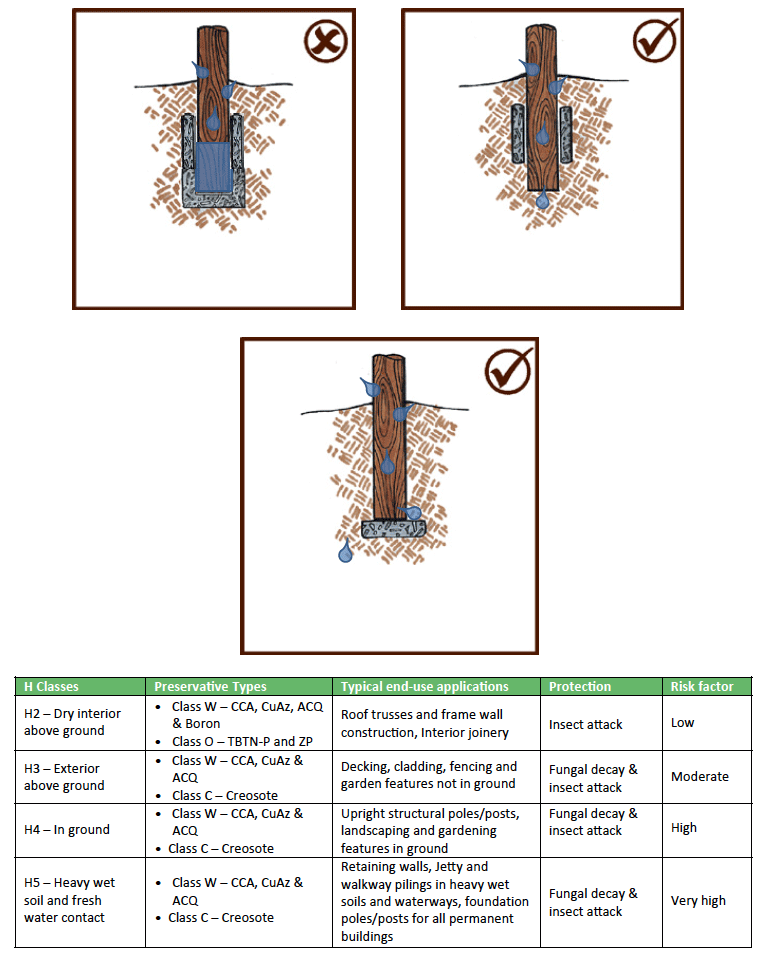
Safety Precautions and Warnings
When machining (e.g. sanding and sawing) CCA treated wood, be sure to wear a dust mask and work in a wellventilated area to avoid inhalation of treated wood particles, and wear safety eyewear to protect your eyes from flying particles. Wear suitable safety gloves when working with freshly treated wood. Do not make toys or furniture from treated wood that may be chewed on by infants, or make any food utensils from treated wood. Do not use treated wood for firewood, or cooking purposes. Treated wood shavings or sawdust should not be used for animal litter or where it can become a component of animal feed.
Disposal
Treated timber waste is not regarded as hazardous waste material; however, treated wood off-cuts and waste should not be allowed to accumulate, but should be disposed of at a registered disposal or landfill site. It is important not to burn treated wood off-cuts as this will allow the release of hazardous chemicals, which are tightly bound to the wood, into the smoke. The ashes will also contain residual chemicals.
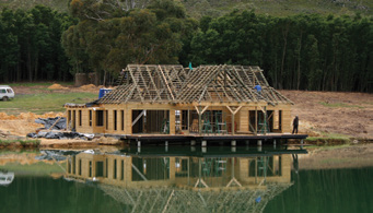
The primary wood preservation industry currently boasts ± 115 certified timber treatment plants in South Africa, consisting predominantly of CCA and Creosote plants. In 2013, the total volume of preservative treated timber manufactured in South Africa was in the region of 1 065 580m3. For more information on wood preservation and where to find a SAWPA member in South Africa, please contact SAWPA at 0119741061 or sawpa@global.co.za or visit our website at www.sawpa.co.za.
Storage of timber
Structural timber stored on site should be stacked on level ground on bearers and adequately protected against the weather by covering with a waterproof material. Air must be allowed to circulate through the timber stacks. Strapping around bundles of battens should not be removed until the battens are to be fixed. This will prevent excessive warping of the battens.
Steel
Refer Roof Construction – Roof trusses – Steel Trusses
Roof pitch and wind forces
The roof as a whole should be designed to with stand the minimum design loadings in accordance with SANS 10160. “The general procedures and loading to be adopted in the design of buildings.” When considering wind forces acting on a pitched roof, the pressure on the windward slope is dependent on the pitch. If the pitch is less than 30°, the windward slope may be subjected to severe suction or to negative pressure. If the pitch is steeper than 35°, the roof generally presents sufficient obstruction for a positive pressure to develop on the windward slope but, even in this case, there is an area near the ridge where suction develops. The leeward side is always subject to suction, though it is usually not as strong as the produced near the windward edge.
When considering pitches of roofs, conditions such as wind speed, shape and locality of building, height and exposure of the roof must be taken into consideration. Recommended minimum pitches for the various types of roofs are described in Table 15.2 – Minimum roof slopes and sheet end laps. Where rain and wind conditions are known to be severe, the roof pitch should, as a rule, be increased by 5° above the minimum.
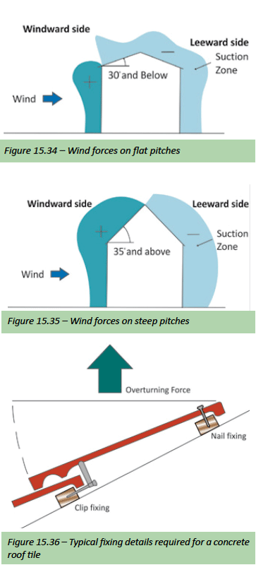
Undertile membranes for roof tiles
In current building practice, the undertile membrane has become an integral part of any tiled roof. When properly laid, it will provide a highly effective barrier against the ingress of wind-driven rain and dust and the pressures exerted by wind forces will be reduced substantially due to pressure equalisation. The use of a suitable undertile membrane which complies with requirement type E of SANS 952 – 1985 or Agrément approved having a nominal thickness of 250 microns (0,25mm) is recommended for all pitches in all areas.
- Undertile membrane must be fixed horizontally over the rafters, prior to battening, with a minimum overlap of 150mm and secured to the centre of the rafters with the minimum number of non-corrosive clout nails. The vertical laps should be secured over the rafters. Do not try and pull the undertile membrane tight. See figure 15.37.
- At closed eaves, the undertile membrane should extend over tilting batten and fascia board to allow drainage of water into the gutter. It should be supported behind the fascia board to prevent it from sagging and forming a water trap. See figure 15.37.
- At open eaves, the undertile membrane should extend at least 20mm over the beam-filling on the exterior wall. See figure 15.37.
- Over a hip, a strip of undertile membrane 600mm wide should be laid overlapping the undertile membrane of the main roof. See figure 15.37.
In valleys, a similar strip should be used and tucked under the undertile membrane of the main roof. See figure 15.37.
Note: It is essential to install a undertile membrane for roof pitches below 26° and above 45° and for all roof pitches in coastal and other exposed and windy areas.
Reflective foil membranes for sheeted roofs
Refer to – Flexible reflective foil laminate insulation (RFL) figures 15.17 and 15.24
Erection of trusses
Failure of roofs can often be attributed to poor workmanship and the disregard of simple erection procedures. Trusses should be protected against any damage on site whilst awaiting erection. They should be stacked on level ground on timber bearers and covered with a waterproof material but with adequate ventilation.
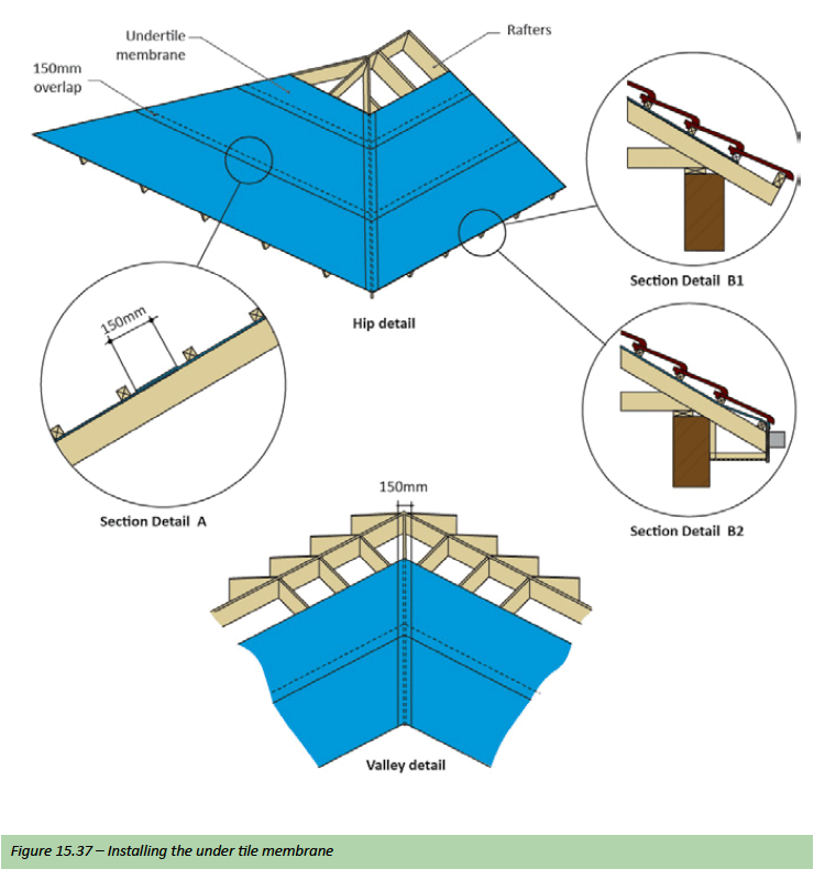
When handling trusses care must be taken to avoid any damage to the timber and to the joints.
- If possible, carry trusses vertically
- With large trusses, sufficient labour should be made available to provide full support avoiding any sagging or whipping when carrying the truss horizontally
- Do not “see-saw” the truss across the walls or scaffolding
- Lift trusses onto the wall in an upright position.
Erection procedure
- Lay the wall plates in position and level. Mark truss centres on the wall plates on either side of the building and ensure that they are square with the gable end of the building.
- Lift the first truss onto the marked position on the wall plate. Plumb the truss and secure in the position using temporary props. Refer to Figure 15.38.
- A further two trusses can now be lifted into position, plumbed and fixed temporarily to the first truss using 38x38mm battens fixed on either side of the ridge keeping the trusses in a vertical position. Fix vertical cross bracing to either side of the king post using 38x76mm M4 grade timber, fixing each connection with two no. 75×3,5mm wire nails. The three trusses attached with cross bracing create a rigid unit to which the other trusses can be attached with temporary battens. These temporary battens and bracing can be removed once all the permanent battens are fixed. Refer to Figure 15.39.
- The remainder of the trusses can be erected, plumbed and attached to the three braced trusses using battens as temporary bracing
- Span a builder’s string line across the rafters of the trusses to check alignment and adjust where necessary using hardboard wedges under the tie-beams of the trusses and skew nail all trusses to wall plate with 100mm nails.
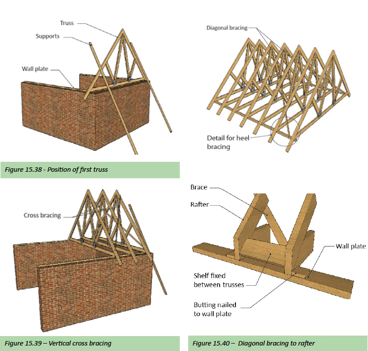
- Permanent diagonal bracing must be installed at the gable ends of the roof. Bracing members must be minimum 38x76mm and should be nailed to the underside of rafters with no. 75×3,5mm wire nails. They must run in a straight line from the apex of the truss to the heel of the truss at approximately 45° and must be connected to the wall plate. Refer Figure 15.40. For spans greater than 6 metres use 38x114mm (Grade 4) bracing members bolted to the underside of shelf with 2 No M12 bolts. Refer figure 15.40 above (detail [standard] – heel bracing).
- To prevent buckling of the long webs (exceeding 1,8 metres), cantilever roofs and the tie beam where no ceiling battens are used, longitudinal runners should be fixed to the members. The runners must be 38×76 nailed to each truss with two no. 75×3, 5mm wire nails at each intersection. All longitudinal runner members must be cross braced. Refer to Figure 15.41.
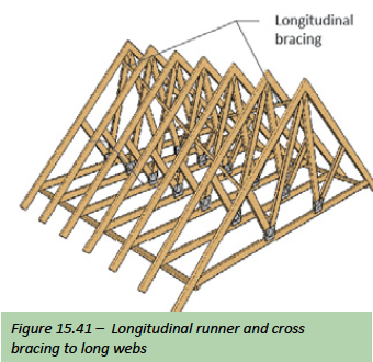
- Having completed all the necessary bracing the trusses must be permanently anchored to the wall and wall plate with the metal straps or galvanised wire which have been built into the wall. Refer to Figure 15.42 below.
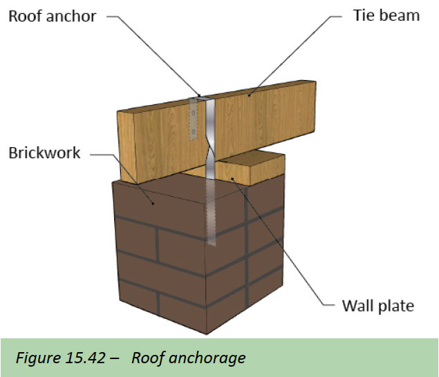
The use of rafters only as roof supports
The use of rafters spanning from wall to wall is a regular feature of modern architecture. The ceiling follows the slope of the roof, or it can be fixed on top of the rafters. Refer to Figure 15.43.
The rafters and wall plate are anchored as previously described, using either 30×1,6mm metal straps or 4mm diameter galvanised wire built into the wall. The rafters must be designed simply supported and the loading uniformly distributed over the full span, in accordance with SANS 10400 Part L.
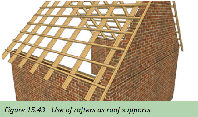
Fixing battens and Purlins
Timber used for battens and purlins must comply with SANS 1783-4. The battens and purlins should be straight, free from major defects and in long lengths. Joints in battens and purlins should be staggered on rafters.
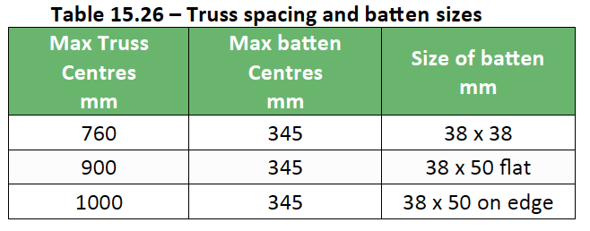
Battens
Size of battens must be in accordance with spacing of trusses. Refer to Table 15.26.] Batten centres will depend on the type of roof tile which is to be used – refer to the manufacturer of the roof tile chosen.
Refer to Superstructure section – Brickwork – Roof anchoring – for more information
Purlins
Any purlin shall have a minimum nominal width and depth of 50 mm and 76 mm respectively and the maximum centre- to-centre spacing between purlins shall be 1,2 m – refer to the manufacturer of the roof sheeting chosen.
Before fixing
The following checks should be carried out before fixing of
the battens or purlins commences.
Check :
- Trusses for alignment/straightness
- Truss spacing
- Truss anchorage to wall and wall plate
- Pitch of roof
- Construction of hips and valleys to engineer’s details
- Bracing of trusses
- Squareness of roof
- Brickwork and plastering to gables, parapets chimney and beam filling has been completed.
Battening procedure
- Establish the roof eaves overhang. Work out the number of full roof tiles to cover the distance from eaves to ridge. To avoid cutting tiles, adjust the eaves overhang allowing for the thickness of fascia plus 50mm overhang of the first row of tiles past the fascia. Ensure that the last of the battens at the ridge is not more than 25mm (for flat profile 25-50mm-refer to manufacture) from the apex. Refer to Figure 15.44.
- Trim rafters at the eaves and fix tilting batten and fascia board. Tilting batten to be 14mm higher than the other battens to ensure roof tiles are in the same plane. Refer to Figure 15.45.
- Fix underlay over trusses by nailing, with the minimum number of non-corrosive clout nails, to the centres of the rafters of the trusses. It is not necessary to fix the undertile membrane tightly over the rafters.
- Mark the batten centres at each end of the roof and strike a chalk line.
- Fix battens according to the chalk lines allowing sufficient overhang at gable ends for trimming. The length of nails for fixing battens should be batten thickness plus 40mm. For a neat fit where the battens intersect at hips and valleys, the battens should be mitred.
- Establish verge overhang using width of full tiles along the eaves and along the ridge. Mark at top and tilting batten only. Strike a chalk line between the two points and cut the battens. Refer to Figure 15.46 on next page.
- If verge tiles are used, the tilting batten and fascia board must extend past the verge counter batten by 25mm to allow for the tilt in the first verge tile.
- With bold profile roof tiles the verge counter batten must be raised above the batten line to ensure good fixing of the verge tiles. Refer to Figure 15.47 – With all the profiles the verge counter batten must be positioned flush with the batten line. Refer to Figure 15.48. The roof is now ready for tiling.
Note: The tiling procedure and the fixing of tiles must all be in accordance with the manufacturers recommendations. Refer to Roof construction at the beginning of this section for more information under rafters and beams and more especially Table 15.6 Maximum spans for rafters.
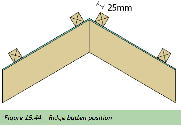
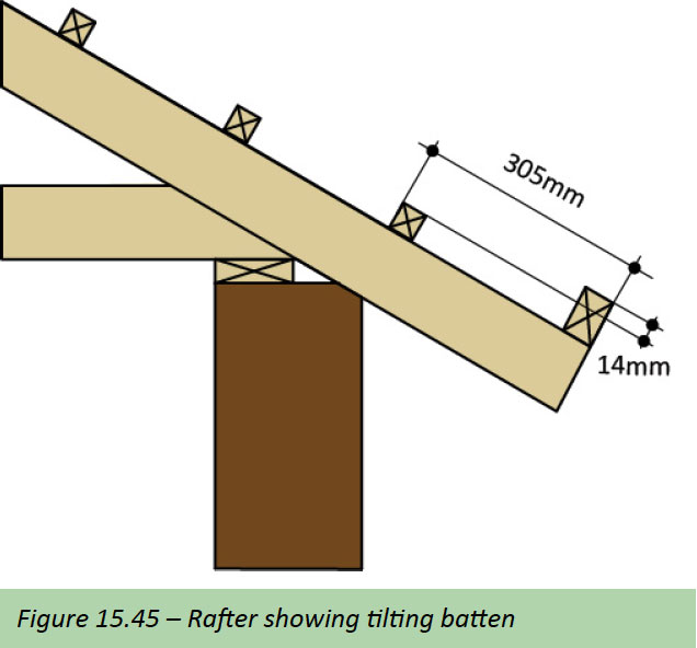
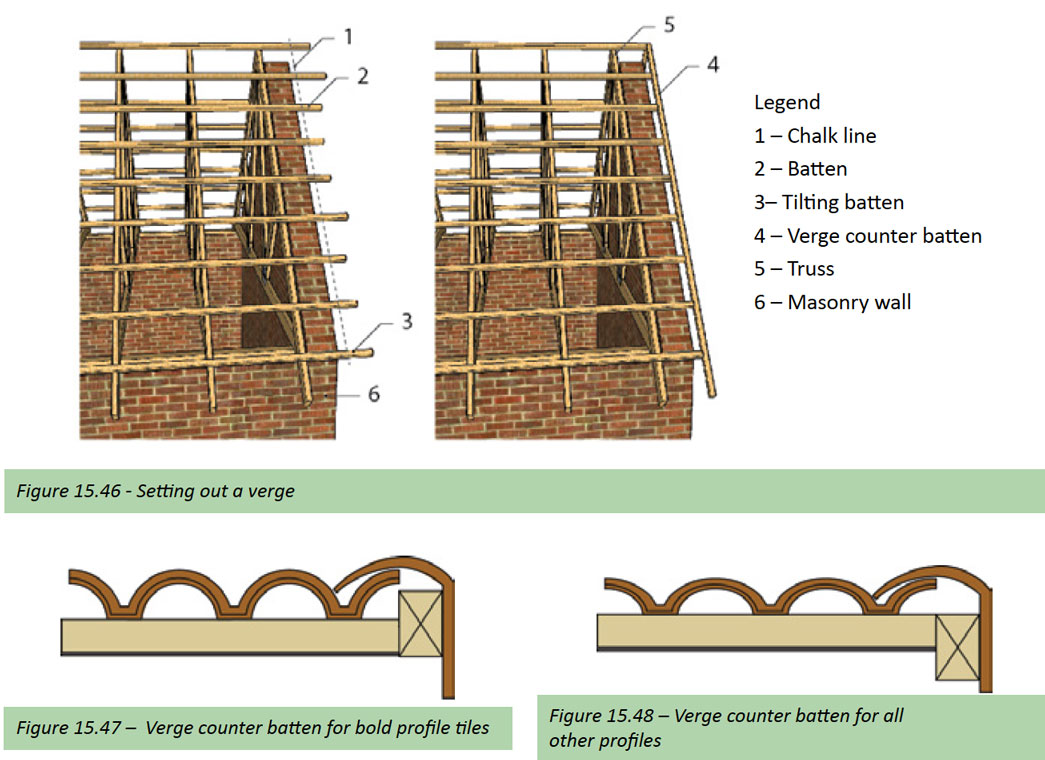
Purlin procedure
- Establish the roof eaves overhang. Work out the required centres to cover the distance from eaves to ridge in accordance with the manufacturer’s specification. Ensure that the last of the purlins at the ridge (apex) is not more than 25mm from the apex.
- Trim rafters at the eaves and fix eave purlin and fascia board.
- . Fix RFL over trusses by nailing, with the minimum number of non-corrosive clout nails, to the centres of the rafters of the trusses.
- Mark the purlin centres at each end of the roof and strike a chalk line.
- Fix purlins according to the chalk lines allowing sufficient overhang at gable ends for trimming. The length of nails for fixing purlins should be purlin thickness plus 40mm. For a neat fit where the purlins intersect at hips and valleys, the purlins should be mitred.
The roof is now ready for the roof sheeting. For sheeting used at the minimal pitch for the profile being used, consideration should be given to the use of a lap sealant at end and side laps.
Note: While we have only briefly described the erection procedure of the two most commonly used roof types – being tile or sheeted – other roofing types are also used which have not been described above; although the fundamentals of each roofing type remain the same it is up to the reader to seek the advice from the manufacturer according to the type of roofing being used for specific specifications and recommendations.
Note: Most pierced fixed roof sheeting profiles should only be fixed at every second crest on internal purlins and at every crest at eaves and ridge (end) purlins. Side laps should be stitched at 500mm centres between purlins all in accordance with the manufactures recommendations.
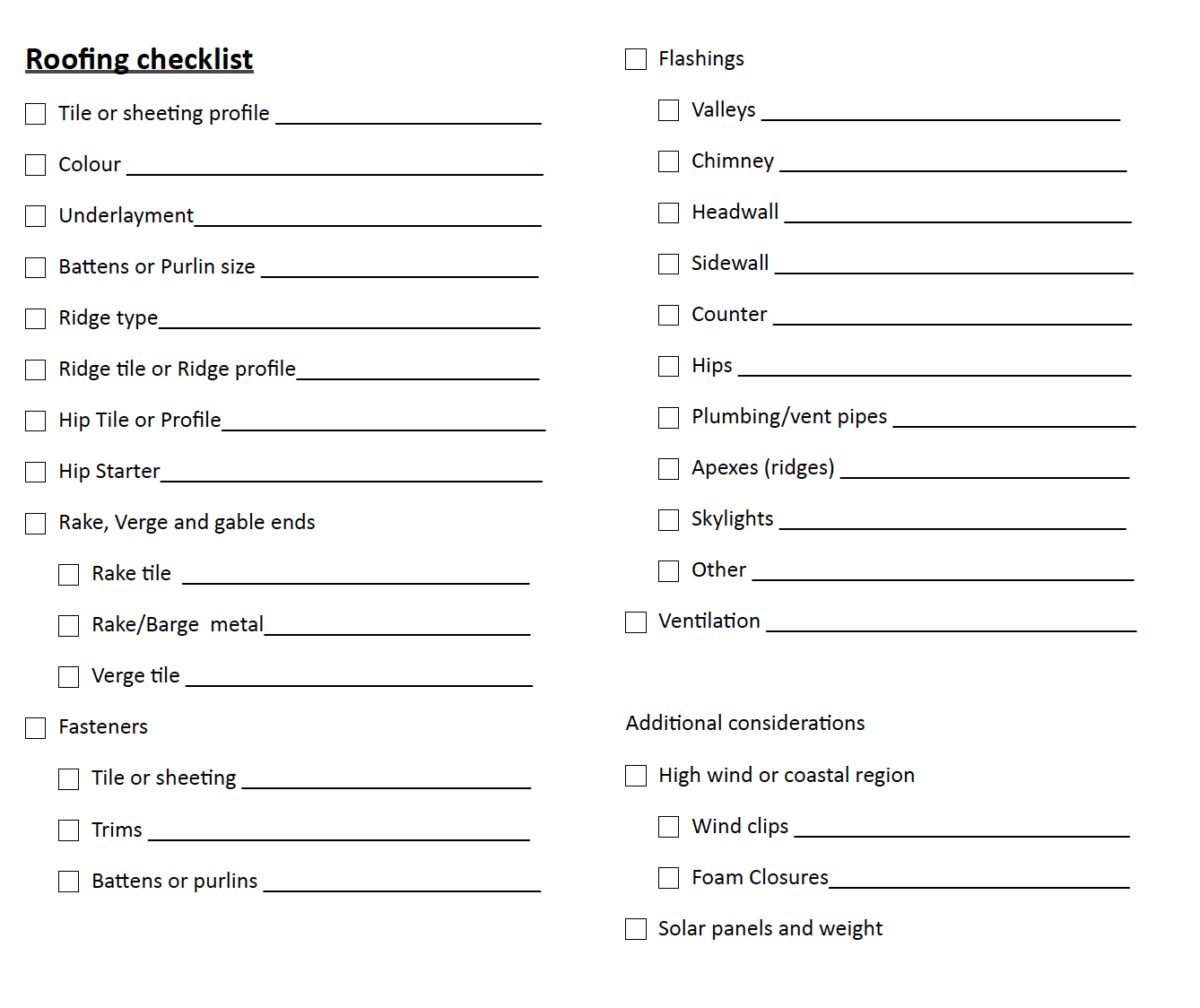
References
Alexander G C. 2010. Energy Saving Building Solutions. Johannesburg: Buildaid Publishing.
Alexander G D & Alexander G C. 2010. Buildaid Building and Pricing Guide 2010/11. Johannesburg: Buildaid Publishing.
Alexander G D & Van As F. 2008: Civil Technology. Johannesburg: EWA Publishing.
Concrete Manufactures Association – Concrete roof tile manual – www.cma.org.za
Julyan E L. 1998. Building & Civil Technology. 2nd Edition. Johannesburg.
South African Bureau of Standards – SANS 10400 Part’s L & various other standards. Pretoria. SABS Standards Division.
Marley Roofing South Africa – www.marleyroofing.co.za
Mervyn Jordan.2004. SA Plumbers’ Handbook: 1st edition. Johannesburg. Pipe Trades Media Group.
Mitek Industries South Africa – www.mitek.co.za
The Institute for Timber Construction – ITCSA – www.itc-sa.org