Chapter 16
PLUMBING
Introduction
Terminology
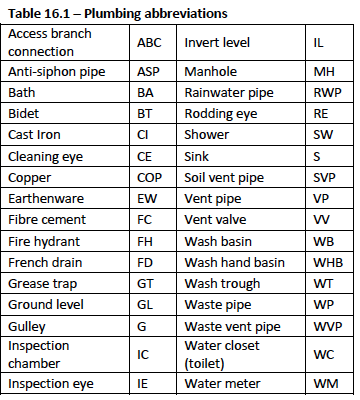
Common Plumbing Abbreviations
Standards
Drainage
Water Supply
Hot Water Systems
Sanitaryware and Other Fittings
Introduction
Water supply or distribution and drainage distribution or sewage pipes form the basics of plumbing, which plays a very important role in the built environment and society as a whole. Plumbing is one of the more regulated trades in the building Industry, where only a registered licensed plumber is allowed to undertake to perform the function of water and sewage installations; to ensure standards and workmanship are maintained.
Of the many trades involved in the building Industry, plumbing has been labeled as one of the more controversial, when it comes to pricing and workmanship. With many unskilled “bakkie brigade” type plumbers undercutting the more professional plumbing operations; added to this undercutting of quotes, is the poor quality of workmanship and the installation of inferior quality or not fit for purpose materials resulting in numerous failures and problems once the building or project is completed.
Terminology
Above ground
Higher than ground level, particularly with reference to the superstructure and to any work after the building is out of the ground.
Access cover
A pipe fitting with a removable plate for inspection, testing or rodding.
Adaptor
A fitting which matches different materials or sizes; for example copper to iron.
Angle valve
A screw down valve with its outlet at right angles to the pipe connection.
Anti-siphon pipe
A branch vent.
Anti-siphon trap
A waste trap which resists unsealing, by having a deep seal of water as found with an S or P trap. (See trap)
Backnut
A nut used to make tight and locked joint as found on long treaded fittings like the connector or on the pipe tail of a pillar tap or mixer or waste fitting.
Ball-valve
Also known as float valve which is a float-operated valve used to control the flow of water into a toilet cistern or a water storage tank.
Basin
A sanitary fitting for rinsing or washing of the hands, often referred to as a washbasin, or wash hand basin with the abbreviation (WHB).
Bath
A sanitary fitting typically with a full length tub and an edge around the rim, available in various forms and shapes.
Bedding
A thick layer of material laid over a surface to fill the irregularities between the substrate and building component. For example, underground drainage pipes are laid on a bedding of riversand; or a bath is laid on a bedding of topping (riversand and cement).
Below ground
A level of work on the substructure and foundations and for buries services like drainage pipes.
Bend
A short length of pipe (fitting) for turning a corner, which also allows for thermal movement in the pipework. For fittings with a 90° bend they are called a quarter bend, a 45° bend is usually called a one-eighth bend. The radii of bends can be quick, normal, or slow and they are less abrupt than an elbow.
Bending spring
A helical spring of circular cross-section inserted into a pipe or tube to keep it circular during hand bending, often after heating with a torch gun.
Bib, bibcock/tap
A water draw-off tap fed by a horizontal supply pipe, not by a pipe from below as found with a pillar tap.
Bidet
A sanitary fitting for washing the nether parts of the body (personal ablutions). The discharge is waste water not soil water.
Bossed connection
A groove in the socket end of a plastic pipe to receive an ‘O’ ring joint.
Branch
A secondary pipe connection to a main distribution or collection system; for example a water distribution system or drainage system.
Branch pipe – discharge
A branch to carry soil water or waste water to the stack.
Branch vent
A pipe which admits air to the downstream side of the water seal in a trap at the start of a drain. The branch vent prevents unsealing of the trap (anti-siphon) as a flush of water passes down the soil stack, as found in a one-pipe drainage system.
Butane
A bottled gas used as a fuel for a blowlamp.
Cap
A cover with internal threads screwed over the end of a pipe –it caps or closes the pipe.
Capillary
The tendency of water (or any fluid) to be sucked into a narrow space such as any close joint.
Capillary joint
A neat, compact joint in copper pipe, made by putting the end of a pipe into a fitting that is slightly larger in diameter, after cleaning the contact surfaces and applying a flux. The pipe joint is then heated until the solder material melts and flows in evenly round the space by capillary action.
Ceramics
Burnt clay-ware (cerami was the potter’s district in ancient Athens), usually meaning high-quality materials made from refined clay and fired at 1000 to 1200°C or higher for fully vitrified ceramics.
Channel
A u-shaped section, such as a half round pipe or formed concrete fitted between drain pipes in an inspection chamber or manhole. Can also refer to a storm water channel to divert stormwater.
Chase
A groove in a wall (or a floor) usually for the building-in of services such as water pipes or conduits – cut into brickwork or concrete using an angle grinder.
Cistern
A water tank used to flush water into a water closet (WC) or more commonly known as a toilet. Most cisterns today have a dual flush mechanism, one button giving a full flush and the other a half a flush. Dual flush cisterns are required by law to save water.
Collar
An enlargement outside a pipe or a reduction within its bore to secure a tight joint between pipes; as in a union.
Compression fitting
A joint usually in copper or plastic pipes made by screwing together the ends of two pipes to be joined by means of inserting ‘O’ rings over the pipe ends which are then pushed into the fitting and a large nut is then tightened compressing the ‘O’ ring around the pipe and into the fitting.
Connector (long screw)
A tubular pipe fitting with a long-screw that has an ordinary taper thread at one end and a long parallel thread at the other, with a Backnut. The length of the parallel thread allows the coupling to be screwed back on to it so that the connector can be removed or replaced without moving the pipe.
Control valve
A discharge valve.
Coupling
A pipe fitting for making joints in different types of pipes. It may be a capillary joint, a compression joint, a sleeve coupling, or screwed, or a connector.
Discharge pipe
A pipe that carries foul water from sanitary fittings.
Discharge stack
Vertical discharge pipe which conveys the discharge from two or more sanitary fixtures and which is connected directly to a drain.
Diverter
A three-way valve as found in a bath or shower.
Drain
A buried pipe that removes foul water from sanitary fittings and takes it to a sewer.
Drainage
A system of buried drains.
Drain cock
A tap placed at the lowest point of a hot water cylinder through which the cylinder can be drained.
Drain plug
An expanding plug which blocks the end of a drain run during a drain test.
Draw-off pipe
The pipe leading to a tap.
Draw-off tap
A water supply tap.
Drinking water
Also known as potable water is water fit for human consumption.
Dual-flush cistern
A water saving WC cistern with a two-button flushing mechanism – see cistern
Ductile Iron
A type of cast iron that is stronger and more impact resistant than grey iron – used for drain pipes.
Elbow
A sharp right-angled (90°) pipe bend
Finished floor level (FFL)
The top surface of a floor screed, the surface from which all levels in a room are taken – this level usually excludes the floor covering.
Flange
A flat plate on the end of a pipe or fitting for making a bolted joint.
Flashing
A strip of impervious material usually galvanised sheet metal that excludes rainwater from the junction between roof coverings and/or another surface, for example a valley flashing.
Floor drain
Pipe fitting into which waste water from the floor is discharged and that is normally connected to a branch discharge pipe, which conveys such discharge to a gully, a discharge stack or an open channel.
Flush(ing) valve
A valve which supplies a precise quantity of water to flush a WC or urinal; typically connected directly to the water mains.
Flush pipe
The pipe connecting the cistern to a WC, urinal or other sanitary fitting, usually connected to the sanitary fitting using a rubber cone.
Flux
A fusible substance used to facilitate the soldering, brazing and welding and prevent oxidation and so help molten metal to stick when joining two pieces of metal together.
Foul (black) water
Water that is contaminated with soil water, waste water, or industrial effluent.
Fully vitrified ceramic.
A ceramic that has been fired at above about 1200° C and vitrified throughout its thickness. It water absorption is below 0,5%.
Gate valve
A valve with a sliding disk which opens to full pipe bore.
Greywater
Greywater gets its name from its cloudy appearance and from its status as being between fresh potable water and sewage water (soil water); it is the water leftover from baths, showers, hand basins and washing machines only; some definitions of greywater include water from the kitchen sink. Any water containing human faecal waste is considered foul water.
Gully (gulley)
An outlet into a drain pipe for water from a floor in a wet area or from a hard surface or for an outside tap to flow into – a trap into which waste water is discharged.
Gutter
A gently sloping channel to collect water and lead it to an outlet or drain. Rood gutters are typically run along the eave of a roof structure, down a valley, behind a parapet. Gutters are also used for roads and large paved surfaces to catch stormwater.
Hard water
Water containing calcium or magnesium salts in solution, which react with soap and thus prevent a lather forming easily.
Head of water
Water pressure, measured in metres of water
Heat exchanger
A device that transfers heat from one fluid to another, for example water/air, or water/water; a typical example of this is a solar panel.
Heat pump
A machine that uses the vapour compression cycle for heating (a reverse cycle air conditioner). The evaporator draws in large quantity of low temperature heat and is designed to move thermal energy opposite the direction of spontaneous heat flow from heat source to heat sink.
Inspection chamber
Chamber not deeper than 1 200 mm and of such dimensions that access can be obtained to a drain without requiring a person to enter into such a chamber.
Inspection eye
Access opening to the interior of any pipe or pipe fitting in a drainage installation provided solely for the purposes of inspection and testing, and to which permanent access after completion of the drainage installation need not be provided.
Instantaneous water heater
A gas or electrical (push through) water heater capable of supplying instant hot water the moment the tap is opened.
Interceptor
A trap that prevents unwanted waste from getting into a drain, for example a grease trap.
Knuckle bend
A pipe bend which turns as sharply as possible
Lagging
Thermal insulation fitted on the outside of pipes to reduce thermal heat loss.
Lip-seal joint
A push-fit pipe joint with a sliding joint ring round the inside of the socket that has an inward-projecting thin blade of rubbery plastic – when a plain spigot pipe end is inserted the lip seal makes a watertight joint.
Longscrew
The parallel threads of a pipe connector
Main drain
Longest run of drain from a building to a common drain, to a means of sewage disposal situated on the site concerned, or to a connecting sewer.
Manhole
Chamber of a depth greater than 750 mm and of such dimensions that it allows entry of a person into such chamber for the purpose of providing access to a drain.
One-pipe system
System of piping between sanitary fixtures and a drain in which both waste and soil water discharge down a common discharge stack and in which any trap venting, or other venting that is required, may be via a common vent stack.
Overflow
An outlet from the highest water level of a storage tank, cistern, bath or gutter. The overflow is connected to a waste or storm water pipe or to a warning pipe.
Percolation rate
Rate at which clean water, under a constant or nearly constant hydraulic head, percolates into the surrounding soil in both vertical and horizontal directions.
Pillar tap
A water tap with a vertical body fed upwards from below through a threaded tail that passes through a taphole in the sanitary fitting.
Potable water
Drinking water
Primary (first) fix
A fixing or service that is built into the structure of a building for the later attachment of a secondary fixture or fitting, for example a water pipe in the wall is the primary fixing while the tap or mixer installed after plaster and tiling is the secondary fixture or fitting.
Resealing trap
Trap so designed that some of the water forming its seal is retained during siphonic action to reseal after siphonage has been broken.
Reducer
A taper pipe or fitting reducing in diameter in the direction of flow.
Rodding eye
Access opening in a drainage installation provided for the purposes of gaining full-bore access to the interior of a drain for internal cleaning, and which remains permanently accessible after completion of the installation; formed by bringing a steep branch back up to ground level and sealing it with a cover plate – but does not include an inspection chamber or manhole
Sanitary fixture/appliance
Receptacle like a bath or basin to which water is permanently supplied, and from which waste water or soil water is discharged.
Sanitary group
Combination of sanitary fixtures comprising not more than one each of a toilet pan, bath, shower and sink and either two washbasins or one washbasin and one bidet.
Septic tank
A tank designed to receive sewage and to retain it for such a time and in such a manner as to secure adequate decomposition.
Sewage
Waste water, soil water, industrial effluent and other liquid waste, either separately or in combination, but does not include stormwater.
Common Plumbing abbreviations
Standards
Plumbing standards and regulations are quite complex and certainly contain volumes of information to vast for this publication. Under this section we have included regulations of a general nature as outlined in the SANS 10400: The Application of the National Building Regulations. We have also referred to specific standards where applicable. The reader should be aware that all standards are subject to review and amendment from time to time as well as new standards being developed. And information about a standard’s current status can be obtained from the SABS offices.
It would also be wise to check specifications with your local authority before commencing with your design or installation, as some regulations do vary from authority to authority.
Gutters and Downpipes
Gutters, downpipes and rainwater goods shall comply with SANS specifications and fixed in accordance with the manufacturers specifications. All rainwater should be discharged away from the walls below DPC level. Where gutters and downpipes are omitted, a concrete apron of at least one metre wide (this is to be approved on site) must be cast around the buildings to discharge water away from the buildings.
Valleys, box gutters and soakers shall be of an approved material, size and design and fixed in accordance with the SANS specifications.
Flashings
Flashings shall be an approved and durable material and fixed in accordance with the manufacturers specifications.
Water supply
Installation of water reticulation systems is regulated by two specific SANS standards
SANS 10252-1: Water supply and drainage for buildings part 1: Water supply installations for buildings, and;
SANS 10254: The installation, maintenance, replacement and repair of fixed electric storage water heating systems; which regulates water heater installations.
Quality of water from local authorities is controlled by SANS 241-2: – Drinking water Part 2: Application of SANS 241-1.
Drainage
All drainage work to buildings shall be carried out by a registered plumber/drain-layer and drains shall be accurately laid to lines and gradients shown on the drainage drawings as approved by the local authority. All drains shall be tested and passed in accordance with the National Building Regulations and the deemed-to-satisfy rules of SANS 10400 – Part P – before the property may be occupied and the drains put into use.
Drainage systems used in South Africa are described in SANS 10252-2: Drainage installations for buildings, and; SANS 10400: The application of the National Building Regulations, Part P Drainage.
Stormwater disposal
Stormwater shall be discharged away from the buildings by means of precast concrete stormwater channels, surface or underground drains. Adequate precautions shall be taken to drain surface and seepage water away from the buildings. The necessary precautions are also to be taken to prevent flooding and damage of surrounding buildings in terms of the local authority.
Visit http://www.sabs.co.za
Visit the SABS online webstore for purchsing standards.
Drainage
Any drainage installation needs to be essentially functional and stable in its operation and should ideally comprise the minimum piping required to remove sewage from sanitary fixtures in a building quickly, quietly and without nuisance or health risk. It is significant that legislation regulating to plumbing work has always been closely and directly related to issues of health, safety and conservation. Attention is given to the requirements of those regulations, codes and standards.
General requirements
So far as standards are concerned, drainage systems outside the building footprint (Below Ground Drains) are covered in SANS 10400: code of practice for the application of the national building regulations, which includes the following aspects:
- Generalities and Definitions
- Connecting Soil and waste Discharge to drains
- Sizing of Drains
- Drain Gradients and Maximum permitted Hydraulic Load
- Venting of Drains
- Installation of Drains
- Maintenance
- Testing of Drains
And, SANS 10252-2: Code of practice Water Supply and Drainage for Buildings, Part 2: Drainage Installations for Buildings. Discharge or (Above Ground) pipe systems used in South Africa are described in SANS 10252-2: Drainage installations for buildings; and SANS 10400: code of practice for the application of the national building regulations: Part P drainage, these are:
- Two-pipe system
- One-pipe system
- Single-stack system
Regulations of drainage installations are carried out by the local authorities, from plan approval to compulsory drainage inspections and final inspection in accordance with the National Building Regulations and the deemed-to-satisfy rules of SANS 10400, before the property may be occupied and the drains put into use.
Definitions
The requirements for drainage systems are generally split between above and below ground. And waste is normally divided into two categories:
- 1. Waste water not containing faecal matter or urine, and 2. Soil water containing faecal matter or urine.
- Any discharge pipe
- That portion of a discharge stack which is below ground level
- The bend at the foot of a discharge stack.
>Above ground drainage connected for the discharge of faecal matter is referred to as “Soil and vent” with a nominal pipe size of Ø 110mm (OD).
Waste water not containing faecal matter is referred to as “Waste” with a nominal pipe size of Ø 40 and 50mm (OD).
Below ground drainage is referred to as “Underground Drain” with a nominal pipe size of Ø 110mm (OD).
“Drain” as defined in section 2 of SANS 10400 means that part of any drainage installation outside a building which is “Below Ground” level but does not include the following:
“Sewer” means a buried pipe which is the property of the local authority that is used for the conveyance of sewage.
“Sewage”, is waste water, soil water, industrial effluent and other liquid waste either separately or in combination, but does not include stormwater.
Above ground drainage (Soil and vent)
Above ground pipework systems should be designed and installed to meet the following performance requirements:
- Liquid and solid wastes from soil and waste appliances should be carried away quickly and quietly without blockage and without the entry of foul air into the building.
- Sanitary discharge pipework relies on gravity flow and should be kept as short as possible, with few bends and adequate pipe gradients for best performance.
- Prevention of foul air into the building is achieved by providing each sanitary fixture with a water-seal trap, either as part of the fixture as found in toilets or as a separate fitting to the outlet of the fixture. The retention of an effective water barrier by protecting trap seals is essential if this design aim is to be achieved.
A trap seal will be broken if changes of pressure in a branch pipe are great enough to overcome the head of water in the trap by self siphonage or induced siphonage and back pressure due to suction (negative air pressure) in the discharge stack.
To prevent failure of the trap seal in order to maintain adequate water seals in the traps of sanitary fixtures, it is necessary to limit changes in the air pressure within the pipe system. The traditional way of doing this is to provide an extensive system of vent piping with the object of equalizing air pressures throughout the system. In the fully vented two-pipe systems, vent pipes are used to ensure that the pressure in the branch pipes never differs greatly from that in the open air.
Research has shown that this can also be achieved by appropriate design of the drainage pipe system itself. This has led to the development of the single-stack system that generally relies for venting on the soil stack alone and whose requirements established by exhaustive research and actual application are also described below.
Two-pipe system
In the two-pipe system, soil water and waste water are separated before the water enters a drain. Soil fixtures discharge to a soil stack that is connected directly to the drain. Waste fixtures discharge into a separate waste stack and enter the drain via a trapped gully, with all traps vented against siphonage.
This system is seldom used, being regarded as uneconomical because of the high cost of the pipework.
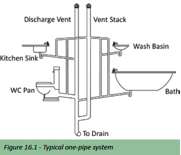
One-pipe system
In the one-pipe system, soil and waste fixtures discharge into a common stack and the system is served by a common vent pipe. The fully ventilated stack system is used in situations where close groupings of sanitary fixtures makes it practical to provide branch vents without the need for trap vents.
All waste fixtures normally have to be provided with antisiphonage pipes but back venting is permitted, provided that waste branches are kept separate from soil branches and that sanitary fixtures are installed in ranges. The system works well and due to the savings in pipework is preferred to the two-pipe system. It is used where the design requirements of the single-stack system cannot be met.
Single-stack system
The Single- stack system can be described as an unvented one pipe drainage system. This is because individual traps are not vented and the stack serves as both the discharge component and the ventilation component of the system. An extension of the system is to provide supplementary dry-venting to the stack when its wet vented capacity is exceeded.
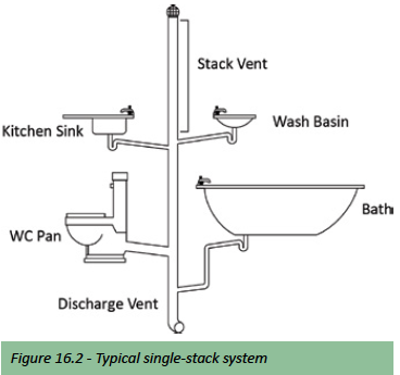
The single-stack system in its basic form as illustrated above compared to conventional systems affords great savings in material, duct space and labour and because of the reduction of pipework, the appearance is less unsightly.
Single-stack is rightly regarded as the most simple and most economical system available in the majority of buildings and hence the most commonly used provided the design requirements are complied with.
Buildings with complex drainage arrangements, such as hospitals or factories are usually not suited to this system. When the design limits as described in SANS 10400 and SANS 10252-2, of the single-stack system are exceeded, the design requirements for the conventional one-pipe system should be used.
Waste
The following general information is provided on waste pipes and what diameter and pipe lengths are best suited to specific applications.
Waste discharge pipes (nominal sizes)
- 32mm Ø Inside dimension = 40mm Ø Outside dimension
- 40mm Ø Inside dimension = 50mm Ø Outside dimension
Wash hand basins; discharge pipes of 32 mm Ø. Lengths and slopes need to be finely controlled if venting is to be avoided.
Banks of wash hand basins; venting is often needed, though not for ranges of up to four WHB’s and pipe lengths up to 4.0 m.
Bidets; the same arrangements apply as for wash hand basins with plug wastes.
Sinks and baths; discharge pipes of 40 mm Ø. Trap replenishment at the end of a discharge means that self-siphonage is not a problem. Restricting the maximum lengths of discharge pipes to 3.0 m will reduce the likelihood of blockages. Combined branch for bath and wash hand basin; it is not possible to give any general design limits, but 40 mm Ø branches and vertical pipes, with 32 mm Ø connections at basins, have been proved to work in practice.
Showers; discharge pipes of 40 mm Ø are normal, though with low flow rates it may be difficult to achieve self-clearing velocities and adequate provision will have to be made for cleaning.
Domestic automatic washing machines and dishwashing
machines; discharge pipes of 40 mm Ø should be no longer than 3 m with a slope of 1 – 2.5°. This can be connected directly to a discharge stack or gully, or to a sink branch pipe. Normally a trap should be fitted in the horizontal section of the discharge pipe, but this is not required for connections via a sink branch pipe, where it can be made at the appliance’s outlet using a suitable fitting.
Urinals; pipes of 40 mm Ø and lengths should be as short as possible but not exceed 3 m.
Below ground drainage ‘underground’
Pipes concealed in the construction of buildings, beneath houses and underground represent to many a vague and mysterious technical area, unglamorous to the extent of being considered unmentionable. Hardly an interesting topic yet, when the system fails, a subject hard to ignore. Those hidden and hardworking pipes, whether appreciated or taken for granted are nevertheless with us as a continuing part of life where certain standards of hygiene, responsibility to the environment, convenience and comfort are expected.
Drain basics
- The nominal diameter of any drain is in no case to be less than 100mm Ø (ID) and the diameter of drains may not be reversed in the direction of flow.
- Where due to the slope of the ground any drain is required to be laid at a gradient steeper than 1 in 5, the hydraulic load carried by the drain shall not exceed the maximum permissible drain loads as described in SANS 10400 Part P.
- Drains of 100mm Ø may not be laid at gradients less than 1 in 150. Special permission from the local authority is required for laying 100mm Ø drains at gradients of 1 in 80, 1 in 100 and, 1 in 120.
- A ventilation pipe shall be placed at a point not more than 6 metres from the head of the main drain and at the head of every branch drain whose developed length, from outlet of the trap of the sanitary fixture to the point of connection to a ventilated drain exceeds 6 metres.
- Where drains pass under buildings, access to the installation must be provided outside of and as close as possible to the building at the pipe entry and exit points and must be laid without change in direction or gradient.
- Permanent access must be provided for cleaning purposes to the interior of any discharge pipe, where it enters the ground and within 2 meters above ground level.
Other pipe sizes and gradients are dealt with in the various documents which exemplify the national building regulations: SANS 10400.
Rodding eyes
Rodding eyes are required to be installed:
Rodding eyes are required to be installed:
- Where there is a change in direction that exceeds 45°.
- At a point within 1, 5 metres of the connection of any drain to a connecting sewer, common drain or to a means of sewage disposal situated on site.
- At such intervals along any drain so that no rodding distance between points of permanent access (such as manholes, inspection chambers and rodding eyes) when measured along the line of the drain is more than 25 metres.
- At the highest point of any drain.
Any rodding eye shall join the drain in the direction of flow at an angle of not more than 45°, continue up to ground level and be adequately supported, marked and protected.
Connection to sewer
The connection of the drain to the sewer is done using a junction fitting; the use of saddles for this purpose is not permitted.
When connecting drains to sewers you must allow flow from the drain to enter the sewer obliquely in the direction of flow so that the included angle between the axis of the drain and the axis of the sewer does not exceed 45°.
Note: “Drain” tests are carried out in the presence of the building control officer or any other officer duly authorized by the local authority. Any material, equipment or labour required for the site testing is to be made available by the installing plumbing or contractor – (see Drainage tests later in this sub section)
Drainage materials
Pipe materials used in the construction of domestic drains and small diameter sewers includes uPVC, cast iron, ductile iron, vitrified clay and concrete. uPVC is the most commonly used material in typical domestic drainage applications “above and below ground”. Cast Iron or ductile Iron is typically used in multi storey buildings and applications where plastics are not suitable. Vitrified clay “Earthenware” is seldom used in domestic applications and concrete typically used for sewer mains and stormwater applications.
Knowledge and attention to detail regarding cutting, jointing, and connection to other materials, trench preparation (bedding) and backfill considerations and loadings are vital to the correct use of whatever pipe material is specified or selected. Drain pipes fall into two categories: flexible pipes; which are made from materials such as plastics, and rigid pipes; which are made from concrete, vitrified clay, ductile Iron or cast Iron. The behavior of the two types of pipe in the ground is significantly different; while rigid pipes have an inherent strength, flexible pipes can deform under the application of loading and require support from the surrounding backfill material to prevent excessive deformation. Linear expansion also needs consideration when using flexible pipes.
The load on a pipeline depends on the diameter of the pipe, the depth at which it is laid, the trench width, type of loading, and the prevailing site conditions. The loading on the pipe itself is also influenced greatly by the type of backfill placed under and around the pipe (Bedding). The choice ranges from placing the pipe directly onto the soil to total encasement in concrete. Flexible pipes are particularly dependent on the backfill material to prevent excessive distortion and, for rigid pipes; there is often a choice between using a high strength pipe on weak bedding or a weaker pipe on stronger bedding.
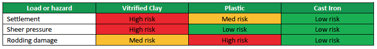
The choice is usually determined by overall economy, although site conditions and material availability may also have to be considered. Especially with small jobs, it may be preferable to choose a pipe requiring minimum bedding requirements rather than have to provide the supervision needed to ensure a more strenuous bedding specification. See table below depicting the risk involved in using various different materials.
uPVC
Unplasticised polyvinyl chloride also referred to as PVC-U to some or uPVC is a relatively stiff “rigid” type of polyvinyl chloride, sometimes brittle in cold weather, impervious to water, oil and many chemicals. uPVC has the advantage of being available in long lengths, lightweight, and easily handled and assembled; making this the most commonly used material in domestic drainage applications.
- Underground pipes and fittings (110 and160mm Ø) are normally beige in colour.
- Above ground “soil and vent” pipes and fittings (110 and 75mm Ø) are normally white.
- Waste pipes and fittings (40 and 50mm Ø) are normally white.
- 110mm soil and drain pipes are typically joined using push-fit fittings and 40 and 50mm waste pipes using solvent welded fittings.
- Structured wall or commonly called ‘Twin-wall’ (heavy duty) piping is used in below ground applications where greater wall strength is necessary to prevent distortion of the pipe depending on loading and other site conditions; Twin-wall piping is also available socketed in 6.00 meter lengths only.
uPVC (PVC-U) Pipes and fittings are regulated by the following standards:
- SANS 791: Unplasticised poly(vinyl chloride) (PVC-U) sewer and drain pipes and pipe fittings
- SANS 1601: Structured wall pipes and fittings of uPVC for buried drainage and sewerage.
- SANS 967: Unplasticised poly(vinyl chloride) (PVC-U) waste and vent pipes and fittings
Cast Iron and Ductile Iron
Iron pipes were traditionally made from crude cast iron (grey iron), however, ductile iron pipes, made from a modified form of cast iron, are now also available. Ductile iron pipes have a much higher resistance to impact than cast iron, and can be struck and dented without fracturing. This makes them particularly useful in situations where there is risk of severe impact loadings; e.g. shallow cover depth below a road.
Although iron pipes are not extensively used for drainage underground, their high strength makes them suitable for applications where special protection would otherwise be needed.
The extended life span of Cast Iron has proven to last 50 years and more. In many buildings it is sustainable longer than other materials, reduces the use of raw materials, and serves the environment further by greatly reducing build-up of waste.
- The coefficients of linear expansion for cast iron and concrete are almost identical. Making Cast Iron a highly suitable material, where drainage systems are required to penetrate concrete floor slabs.
- No special jointing to allow for differential expansion is needed. (expansion compensators)
- The interior surfaces of PAM-SMU pipes are optimally protected against chemical and mechanical influences as a result of a newly refined coating process on a modified epoxy-resin basis.
- Moreover the new extremely smooth surface has improved the flow properties and prevents the formation of incrustations and deposits.
- The inner coating of cast Iron pipes and fittings has been coordinated in an ideal manner so that no differences can arise in the durability values of PAM-SMU drainpipes.
Besides the fixing required by fittings, modern Cast Iron drainage systems only need load bearing support every 3 metres. Jointing with SSN (1) couplings can be done quickly and easily, even with semi-skilled labour. And less hanging & fixing is required due to the rigidity and strength of Cast Iron.
Iron Pipes and fittings are regulated by the following standards;
- SANS 746: Cast Iron pipes and pipe fittings for use above ground drainage applications.
- SANS 1835: Ductile Iron pipes, fittings, accessories and their joints, for use in high and low pressure systems for potable and foul water.
Different diameters of cast Iron pipes and fittings range from 50mm up to 150mm, available in lengths of 2 and 3 metres. Diameters of Ductile pipes and fittings range from 80mm up to 2000mm, available in lengths of 2 meters and upwards depending on the diameter of pipe.
For further details contact PAM – Saint-Gobain Pipelines SA. www.saint-gobain.co.za
Vitrified clay
Most drains constructed up until the 1960s, will be Vitrified or fired clay. The pipes produced were of 4” and 6 “diameters and lengths were limited to 2 or 3 ft by the risk of distortion during firing. Jointing was by caulking with hemp yarn and forcing Portland cement based mortar into the socket. If the hemp was not fully inserted, there was a risk of mortar protruding into the pipe, which explains the old procedure of dragging a ball of sacking through the pipe immediately after laying and before testing. The joints between the pipes were obviously rigid and therefore extremely susceptible to damage from ground movement.
During the 1960s and 1970s practice changed considerably, with the introduction of fired clay pipes which were no longer glazed. These pipes have proved to be no less suitable for a given usage than the older glazed variety. There is no significant difference in hydraulic resistance in service; the modern pipe with its greater length and more accurate jointing may often prove superior.
- The performance of modern clay pipes has been vastly improved by the introduction of flexible ‘O’ ring seals and plastics couplings.
- Vitrified clay pipes remain popular because of their resistance to attack by a wide range of substances, both acid and alkaline.
Vitrified clay pipes and fittings are regulated by the following standards;
- SANS 559: Vitrified clay sewer pipes and fittings.
Pipes and fittings are available with nominal bores of 100mm upwards; in lengths of 0.3 – 2.5 m and, depending on size, in different strength classes.
Concrete
Concrete pipes are suitable for use with normal effluent, but may be attacked by acids or sulfates in the effluent or in the surrounding groundwater. Concrete pipes are used mainly for sizes of 300 mm diameter and upwards; Concrete pipes are supplied either reinforced or un-reinforced.
Joints are usually the spigot and socket type fitted with push-fit flexible rubber ‘O’ ring seals or are ogee joints for use with cement mortar or proprietary bitumen based compounds. Cement mortar joints are unlikely to remain watertight and should be used only where some leakage into or out of the drain is acceptable (e.g. Stormwater). Similarly, although using bitumen based compounds will provide some flexibility, it is difficult to guarantee the water tightness of this type of joint.
Concrete pipes are regulated by the following standards;
- SANS 1200: standardized specification for civil engineering construction: Section DB: Earthworks (pipe trenches); Section LB: Bedding (pipes); Section LD: Sewers
- SANS 677: Concrete non-pressure pipes
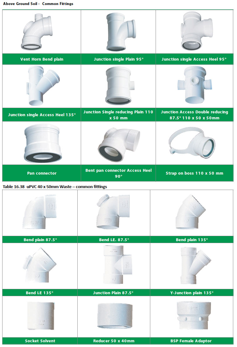
Typical pipe fittings
With other material types like cast Iron, ductile Iron and vitrified clay, being seldom used in domestic/residential applications we have only included uPVC fittings, although the terminology of fittings is somewhat universal across different material types.
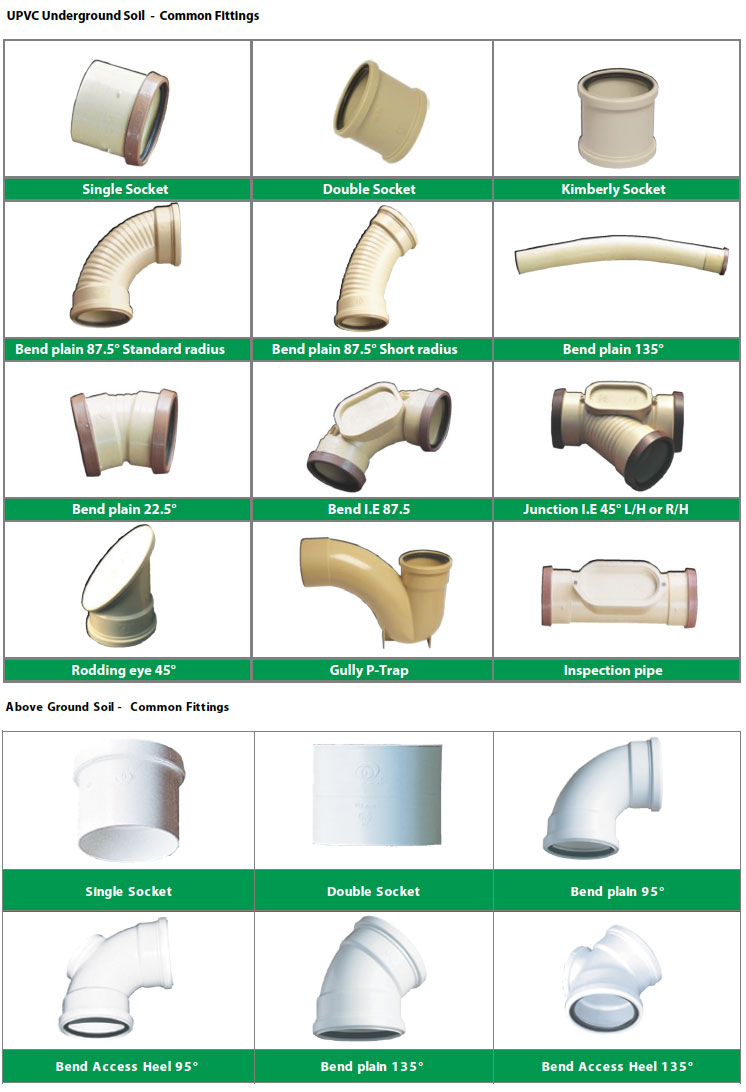
Note: Push-fit fittings available for 110mm pipe either as loose couplings or integral sockets provide some telescopic flexibility. Solvent welded joints used for waste fittings do not permit axial movement, but small changes of length caused by thermal movement can usually be accommodated by axial tensile or compressive strain in the pipe material.
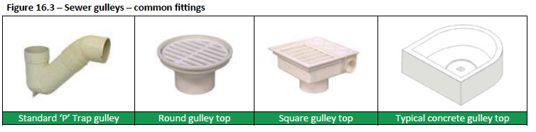
Gulleys
Gulleys are not only part of sewer “drains”, they can also be used as outlets for stormwater or as surface outlets for the disposal of water used for washing down floors in bathrooms or kitchens. Surface gulleys remove water or stormwater from the vicinity of buildings, and other hard surfaces, to appropriate disposal points. The major difference from sewer drainage is in the provision of access, including intercepting traps and trapped gulleys. The latter two are needed only where the system eventually connects to sewer drain. Gulleys, whether trapped or not, should be provided with grates to prevent the possibility of foreign substances entering the drain.
Various investigations have shown conventional gulleys to be the main cause of flooding in sewer networks. This is largely the result of malpractices such as the discharge of rainwater directly into open gulleys or, when surface water is sloped so as to direct such runoff in the direction of the gully. For reasons as described above, many local authorities have taken steps to cut down on the prolific use of open gulleys or inspection chambers as a means of stormwater disposal; with some local authorities actually not allowing it at all.
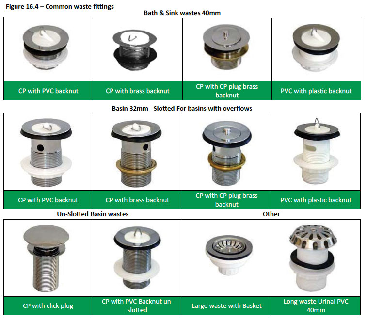
Wastes
A waste union can be described as a threaded outlet pipe fitted to the plug hole of a basin, sink, wash trough or bath. It has a flange that goes on the inside and typically a smooth collar which is inserted through the sanitary fixture (in the case of a basin waste it can be slotted to allow for the fitted overflow to discharge into the waste). On the outside of the fixture it has a threaded tail pipe to which a sealing washer and back-nut are tightened to secure the waste union to the sanitary fixture; to which a trap is usually then fitted over the treaded tail (see traps).
- Wastes are also available with fitted chains commonly termed “Waste, Plug and Chain”
- Also available are pop up wastes, which are supplied with the actual mixer as the lever which operates the plug or seal forms part of the mixer.
- Push button or as some call “Click- Click” wastes are becoming more and more popular.
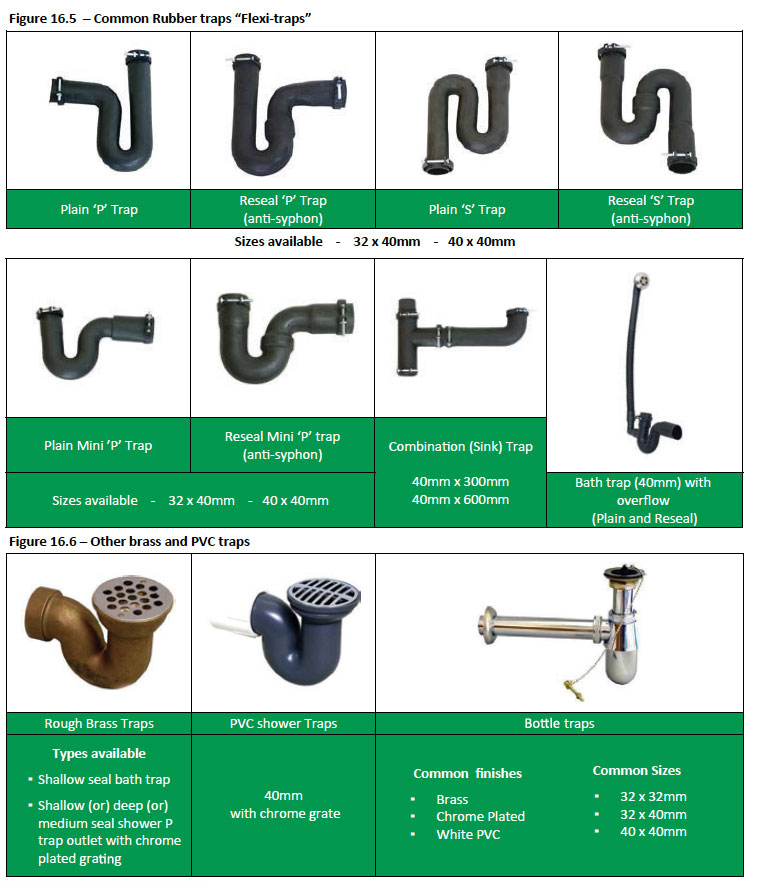
Traps
Traps are fitted to sanitary fixtures to allow a water-seal to form in the trap to prevent foul air emanating from the wastes of such fittings and are available in a number of different variations and manufactured from Rubber, plastics and brass and finished in a number of different ways e.g. “CP” Chrome Plated.
Designer bottle traps are also available and manufactured by a number of different suppliers in many variations, sizes and finishes; ask your local Massbuild store for more information.
Drainage tests
It is obvious that building regulations play a very important role when it comes to plumbing and they fulfil a very important purpose associated with this trade and thus cannot be ignored. It is also important to note that all local authorities apply these national building regulations coupled with their own by-laws. It is therefore imperative that the local council be consulted before any plumbing work and more especially drainage is undertaken.
The duty of the local council is:
- To check all building plans related to the drainage and water distribution layouts of a specific project in relation to its location and building type to ensure they comply with all the required regulations before any work may commence on site.
- To test the soundness of the drain (if required) and to ensure that there are no leakages before the plumber is allowed to backfill the drain trenches.
- To inspect the work at other intervals (as required) during and after completion to determine whether the work has been done according to the approved plan(s) and to ensure the materials used and workmanship are to standard.
Water Supply
After entering the building the water supply line now becomes the “Water Distribution system”. At this point it will be divided to direct water to a water heater (geyser) and a cold water supply to all of the familiar Sanitary-ware fittings and appliances (including the hot water supply where required) that we utilize for our daily use.
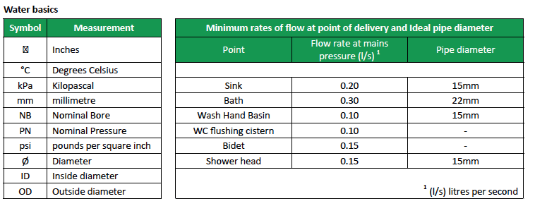
General requirements
Water supply pressure has a large influence on the sizing and grade of reticulation pipe work. For gravity fed low-pressure systems the pipe work can be as large as 25mm. For higher pressures, pipe sizes can be reduced to 15mm. The length of pipe run also plays a large role in delivery of water; the longer the pipe, the greater the resistance to flow and hence a lower volume and pressure at the point of delivery.
In the case of dwelling houses, it will usually not be necessary to carry out a detailed exercise to size the pipes for the installation. For the internal hot and cold water supply systems, certain basic pipe sizes will be generally applicable. The service pipe between the boundary and the house should be sized. Where automatic shut-off valves are used in lieu of cisterns for WC’s, it will be necessary to size the pipes supplying such valves.
In terms of standards and pending legislation there are new regulations being discussed that will soon be applied; whereby the water distribution system to all buildings, including dwelling houses, will have to be designed by a competent person and detailed on the plans showing all main and branch pipe sizes, sanitary fixtures etc. for approval by the local authority – similar to the schematic shown under Typical Plumbing Layout at the beginning of this section.
Average water consumption figures
- A bath uses about 80 – 90 litres
- A shower 30 litres (a powered shower may use more)
- A dishwasher 20 – 50 litres
- A washing machine 100 litres
- Old standard flushes for WCs took up to 13 litres whereas newer models use as little as 6 litres
- A hosepipe can use between 600–1000 litres per hour
- Total household water consumption averages around 140–190 litres per person per day.
Cold and hot water distribution
Cold water distribution Cold water supply pressures vary tremendously, depending on the source of supply. Pressures may vary from 100 kPa to 2000 kPa. Due to this large variance the provision for balancing of hot and cold water pressures is compulsory in terms of SANS 10254.
A pressure control valve should always be installed at the entry point of the cold water supply to buildings. If a low pressure system is installed the valve will need to be installed near the Hot Water Cylinder – SANS 10254 requires that it not be more than 2 Metres below the HWC in order for optimal pressure to be obtained. Maintenance and cleaning of the pressure control valve is also made easier to access when installed on the outside (see pressure control valves under Hot water systems electric geysers) Guidelines for the maximum distance from the water heater (geyser) to the pressure control valve are:
- 400 kPa system 15m
- 600 kPa system 30m
Hot water distribution
Hot water distribution normally takes place from the geyser (water heater). The geyser (for domestic purposes up to 450 ℓ) is manufactured to SANS 151: fixed electric storage water heaters. The design of geysers is also regulated in the occupational health and safety act; which requires that the water is kept below its boiling point at atmospheric pressure, and that an air cushion may not form in the water heater. For this reason the hot water outlet of the geyser must always be at the highest point.
The maximum allowed temperature that is allowed at a terminal fitting is 58⁰C. Therefore water for domestic purposes is only needed at temperatures below 100 °C; an explosion cannot result when water is released at these temperatures however high the pressure. Accordingly, the Building Regulations specifies that there shall be adequate precautions to prevent the temperature of stored water exceeding 100 °C.
These precautions usually include:
- a failsafe thermostat
- a temperature and pressure safety valve (T&P valve)
These are designed to operate in sequence as the temperature rises. For the water temperature to exceed 100 °C, all three means of protection must have failed.
Water boils at 100 °C at sea level and at lower temperatures as the altitude increases. For pressurized water heaters the water boils at higher temperatures (super-heated water) i.e.
- 120 °C at 100kPa
- 151 °C at 400kPa
- 165 °C at 600kPa
If water at elevated temperatures and pressures is released back to the atmosphere, the excess temperature above 100 °C flashes off as steam. This change of state from water to steam is what creates the violent explosions associated with geyser explosions.
From the above it can be seen that the operation of the temperature and pressure safety valve and fail-safe thermostat are critical. (See hot water systems for more information)
With regard to the hot water supply pipe, the following needs to be determined:
- The lengths, and
- The sizes in accordance with the demand from the fixtures to be served and in accordance with point 7.6 of SANS 10252-1:2012
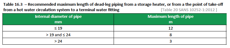
Unless otherwise stated, the length of an unheated pipe (dead leg) conveying water direct from a fixed water heater to a terminal water fitting, or from the point of take-off from a hot water circulating system to a terminal water fitting, shall be such that the internal volume of that pipe does not exceed 4 Litres.
The internal volume of pipes and permissible lengths in terms of the 4L volume limit are given in table 16.2 and recommended limits are given in table 16.3.
The objective is to provide hot water at the locations, in the quantities and at the temperatures required by the user, in the most economical way.
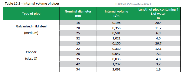
Note: Apart from the volume limit, more than just the internal volume of the pipe might have to run to waste before water of sufficient temperature emerges from the tap, since the hot water has to fist heat up the pipe. For example a tap in wash basin supplied by a 15mm diameter galvanised mild steel pipe 12 m in length and discharging at 6 L/min, would have to run for 1 to 2 minutes before the temperature of the water entering the basin is adequately hot. Thus, the volume of water run to waste would be 6 L to 12 L, whereas the actual internal volume of the pipe is only 2,4 L. The designer should therefore attempt to ensure that where practical, the lengths of such pipes are well below those as illustrated above in column 4.
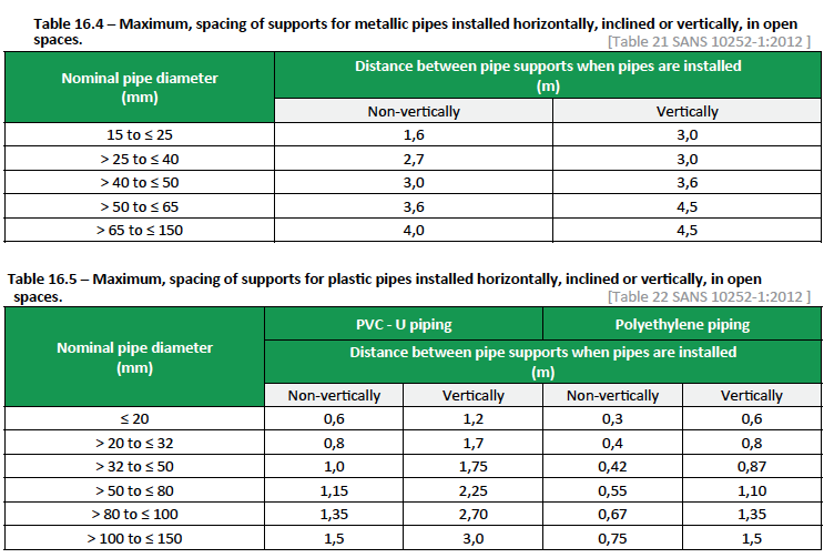
Pipe movement and support
Pipe movement needs to be considered when designing a water distribution layout; which is based on the type of pipe being used. Pipe fixing (where required) needs to allow for this movement and must not hold the pipe so tightly that it cannot move through the fixing to prevent rupture of the pipe or joint; especially when installed in roof applications; concrete slabs or in the wall.
Quite often joints on long lengths of pipe pull out when the pipes contract during the cold of night if the pipes are fixed during the high heat of the day and no provision for movement has been made. Take special care where the pipe is between fixed points i.e. an external pipe running between elbows or tees going straight into walls. Provision for expansion could include the forming of expansion loops and offsets, introducing changes in direction in order to avoid long straight pipe runs and the fitting of
proprietary expansion joints. Expansion loops and off sets are simple and effective but require space, which might not be available. Pipe support and fixing when installing pipes in exposed applications is vitally important to prevent rupture and potential leaking, especially when under high pressure. Fixing of pipes to walls or trusses using bent nails is not recommended. Pipe supports shall be of a type and material appropriate to the pipe material and should be corrosion resistant when pipes are installed in locations exposed to corrosive elements.
Note: Copper holder-bats should not be used for the fixing of steel piping.
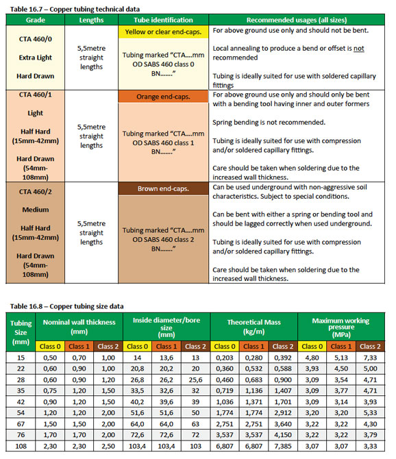
Thermal insulation
Pipes, fittings and components shall, when necessary, be protected against freezing. The insulation provided shall be appropriate to the minimum temperatures that can be expected in that geographical area. All exposed pipes to and from the hot water cylinder(s) and central heating systems shall be insulated with pipe insulation material with a thermal resistance (R-value) measuring unit (m². K/W) in accordance with Table 16.6. Insulation should:
- Be protected against the effects of weather and sunlight
- Be able to withstand the temperatures within the piping, and
- Achieve the minimum total R-value given in Table 16.6.
Piping to be insulated includes all flow and return piping, cold water supply piping within 1m of the connection to the heating or cooling system and pressure relief piping within 1m of the connection to the heating or cooling system Hot water vessels and tanks shall be insulated with a material that achieves a minimum R-value of 2.
Note: To achieve this value, insulation in addition to the manufacturer’s installed insulation might be required.
Water pipes
Oddly, there is nothing about a 15mm (½”) pipe that is 15mm (½”) ; be it copper, galvanized iron, or Polyethylene. The outside diameter of copper is 16mm, and the inner diameter is 13.4 mm, 13.8mm or 14.5mm, depending on the class. Socalled 15mm (½”) galvanized iron pipe has a 21mm outside diameter and a 15.8mm inside diameter. Pipes are manufactured from various different materials which are discussed in more detail later in this section; they are available in a number of different sizes and grades or classes.
- Grades or classes relate specifically to the wall thickness of the pipe, its location and whether it is to be used in a high or low pressure application.
- Pipe diameters are based on the old imperial (inch) size and in many instances are still referred to, in these inch sizes today. The metric sizes used do sometimes differ from material to material, as some refer to the nominal metric pipe diameter and not the actual outside pipe diameter; as shown in the table below.
- Outside dimensions (OD) of pipes can differ substantially depending on material and wall thickness. The nominal inside diameter (ID) can also differ depending on the type of pipe e.g. a 15mm galvanized pipe has an actual outside diameter (OD) of 21mm.
Fittings
Fittings are somewhat generic in description regardless of the material being used i.e. a copper bend is an elbow as is a galvanized bend an elbow; the only differences being some have a far greater variety of types of fittings to choose from.
Note: A bend is normally made up of a large radius fitting i.e. a galvanised m&f bend or spring bend where as a sharp bend is referred to as an elbow.
Sizes of fittings are manufactured to suit all pipe sizes and variations of different pipe sizes or materials. Sizes Distribution systems for domestic houses and other similar small installations can usually be sized easily on the basis of experience and applicable standards. In general, the mains that serve fixture/point branches can be sized as follows:
- Up to three 10mm branches can be served by a 15mm main.
- Up to three 15mm branches can be served by a 20mm main.
- Up to three 20mm branches can be served by a 25mm main.
Material types
Copper
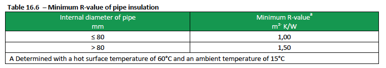
Copper can be described as a metal that is durable, malleable and easy to work with. It also has good electrical and thermal conductivities. Copper tubing can be supplied in one of three different conditions;
- annealed (soft)
- half hard, and
- hard drawn
Copper tubing in a coil is invariably annealed, which makes it easy to straighten and bend and typically used in air-conditioning and gas applications. Hard drawn tube has the least wall thickness but is difficult to bend.
Copper comes in various grades, the most common domestic copper tubing known as “Class 0” or 460/0 used mainly inside homes is hard, light gauge thin walled; classes 1, 2, and 3 are available with thicker walls which are recommended to be used outside the home and the thickest when being cast into concrete slabs and other exposed applications.
See Tables 16.7 and 16.8 below.
Did you know?
The Earth has somewhere in the region of 1234,000,000,000,000,000,000 litres (1234 million trillion litres) of water on the planet. Roughly 98% of our water’s in the oceans of the world, and therefore is unusable for drinking because of the salt content. That means only around 2% of the planet’s water is fresh, but 1.6% of that water is locked up in ice caps and glaciers. Another 0.36% is found in very deep, underground sources – meaning only about 0.036% of the planet’s total water supply is found in lakes and rivers (our main source of drinking water.
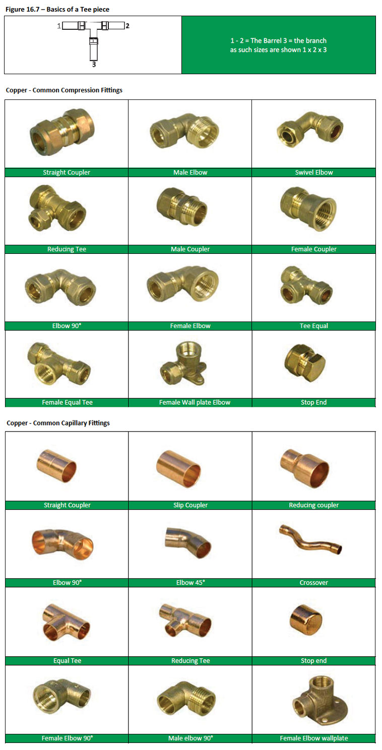
Copper fittings are broken into two distinct types:
- Compression and
- Capillary
Compression fittings
Are fittings where the end of a pipe is inserted through the cap-nut then the gland ring then into the coupling where the nut is then tightened compressing the pipe and gland ring into the fitting, creating a water tight joint. Typically used with class 1-3 copper tubing and can be used with polypropylene piping if an insert is used to support the piping.
Capillary fittings
Are fittings where the end of a pipe is put into a slightly larger in diameter fitting after applying flux. The pipe joint is then heated with a Blow torch until the solder melts and flows in evenly into the space by capillary action.
Some typical abbreviations used with copper tubing and fittings
C: Copper
C x C: Copper x Copper
C x C x F :Copper x Copper x Female
C x C x M: Copper x Copper x Male
When specifying the sizes on a tee the barrel is first mentioned and then the branch
Polyethylene (PE)
Polyethylene piping is also commonly referred to as “black water pipe” and typically used in cold water mains supply and irrigation systems. It can be bent cold to a fairly large radius or given a permanent bend using heat or boiling water (only if thick walled), available in two forms, high density (HD) and low density (LD).
It is important to remember that High Density Polyethylene (HDPE) cannot handle constant temperatures exceeding 60°C if used in pressure applications. In non-pressure applications the temperature generally cannot exceed 80°C. HDPE can handle operating temperatures below –18°C.
HDPE
High Density Polyethylene (HDPE) pipe is lightweight, flexible, durable and corrosion resistant with excellent flow rates. HD pipe is very difficult to bend in small radiuses and pipes used in high pressure domestic applications are typically joined using non-manipulative polyethylene compression fittings. PE is used for a variety of applications and comes in all pipe sizes, lengths and pressure ratings/classes
- Type 3 LDPE: Inside Diameter Pipes. Sizes Ø 15- 80 mm. Class 6. Usually uses Nylon Insert Fittings or Galvanised Steel Fittings, which fit on the inside of the pipes.
- Type 4: Outside Diameter Pipes, Sizes Ø 20-110 mm. Classes 6,10,12,16 and 20. Usually uses Compression Fittings, which fits on the outside of the pipes.
- Type 5: Outside Diameter PE63 comparable pipes. Sizes Ø 125-200 mm. Classes 6, 10, 12 and 16. Usually stubs and flanges are welded onto the pipe for jointing. Other jointing through welding also possible.
The pipe wall thickness of the pipe determines the pressure rating: the lower this rating the thinner the wall. If you need a pipe that can handle a pressure of 6 bars – then choose a class 6 pipe. The class thus indicates the pressure which a pipe can handle.
HD pipe used in domestic applications is typically type 4; classes 6, 10 and 12 which provide a high resistance to fracture and fatigue.
Applications:
- Irrigation; golf courses and most domestic and commercial irrigation systems.
- Bulk Water Reticulation; Water supply projects, municipal water mains etc.
- Electrical: Clients are electrical contractors; a smooth wall conduit used to house and protects sensitive electrical and utility cabling. Provides outstanding mechanical protection to most electrical cable.
- Communication: HDPE fiber optic conduit is considered the best protection for telecommunications and electrical power transmission lines
LDPE
Low Density Polyethylene (LDPE) pipe is extremely lightweight, flexible, durable and corrosion resistant with excellent flow rates. LD pipes are recommended for low pressure applications and come in all pipe sizes, lengths, and pressure ratings/classes;
Type 1: Inside Diameter Pipe Sizes Ø 15- 80 mm Class 3 and 6. Usually uses Nylon Insert Fittings, which fits on the inside of the pipes.
Applications:
- Irrigation; DIY and domestic irrigation systems. PE pipes are available in rolls of 50m and 100m and sold by the metre by some suppliers.
Polyethylene fittings are broken into two distinct types:
- Compression fittings, and
- Nylon insert fittings
Compression fittings
Are fittings where the end of the pipe is inserted through the hand-nut and the nylon gripper ring, which is then pushed into the coupling/fitting where the hand-nut is then tightened compressing the pipe and seal into the fitting, creating a water tight joint.
Nylon insert fittings
Are fittings where the end of a pipe is pushed through a hose clamp and over the insert fitting which has a similar diameter as the ID of the pipe. Once the pipe is over the fitting the hose clamp is tightened.
Note: These fittings are not recommended for high pressure applications.

Polypropylene (PP)
Stronger and more rigid than polyethylene, polypropylene (PP) is one of the toughest plastic pipes available, having a higher functioning temperature and unaffected by chemicals found in water. It has good resistance to sunlight, but lasts longer if fully protected.
Polypropylene commonly referred to as “polycop” is used in plumbing for cold and hot water. This pipe is available in different sizes Ø 15mm, 22mm, 28mm, 35mm, 42mm and 54mm. Available in rigid lengths of 6.00m or in rolls of 30m, 50m and 100m.
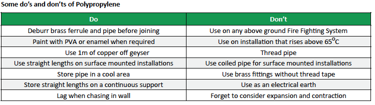
Fittings
Polypropylene pipes are joined using brass compression fittings (see copper above)
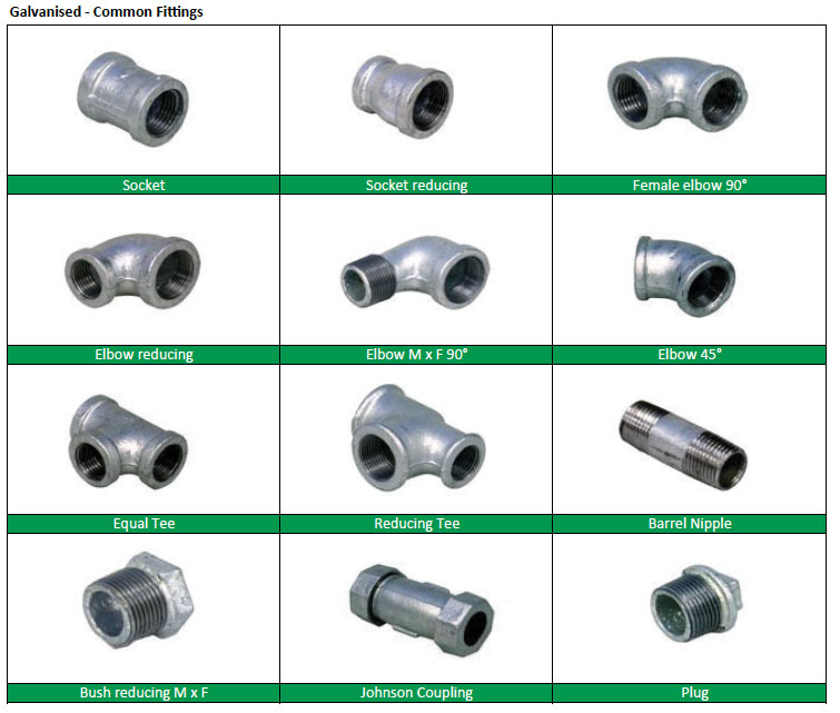
Galvanized Iron
Galvanizing is an actual coating of zinc on steel pipes which is quite hard and gives protection against mild or moderate exposure and does corrode when exposed to chemicals and dissimilar metals. The main problem with galvanized piping is that water will be severely restricted by corrosion that eventually fills the pipe completely. Another problem is the mismatch of metals between the brass valves and the steel. Whenever steel pipe meets copper or brass, you will see rapid corrosion of the steel pipe.
SANS 62 has been revised and the 2001 edition no longer makes provision for Light gauge pipes.
Unless otherwise specified, pipes shall be threaded taper thread; Galvanised pipes are threaded after galvanizing. Threading is not recommended for Light pipes; however, should threading be necessary, standard pipe fitters’ dies may be used. The use of parallel threads on Light pipes is not recommended. All threading conforms to SABS 1109-1: Pipe threads where pressure-tight joints are made on the threads.
Coatings
Pipes of 15mm nominal bore and over are available uncoated, coated or galvanised inside and outside in accordance with SABS EN 10240 (minimum galvanised coating thickness 55 microns on the bore).
Marking
All pipes are identified by means of colour bands as follows:
All pipes are identified by means of colour bands as follows:
- Light pipe – Two Brown Bands.
- Medium pipe – Two Blue Bands.
- Heavy pipe – Two Red Bands (alternatively, the whole pipe may be painted red).
Pipes are available in the following sizes Ø ; 15mm, 20mm, 25mm, 32mm, 40mm, and 50mm (bigger pipe sizes are available) Pipes are supplied in standard lengths of 6 metres, in light, medium and heavy grades. Borehole exacts are supplied in lengths of 3 metres.
Some typical abbreviations used with galvanized pipes and fittings
BSP – British Standard Pipe Thread
BSPT – British Standard Pipe Taper Thread
F x F – Female x Female
F x M – Female x Male
FI – Female Iron
M – Metric Thread
M x F – Male x Female
M x M – Male x Male
MI – Male Iron
Did you know?
If a drip from your tap fills an 240 ml glass in 15 minutes, it will waste 681 litres per month and 8,176 litres per year
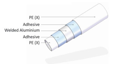
Multilayer composite – (PEX)
PEX is an acronym for cross-linked polyethylene. The “PE” refers to the raw material used to make PEX (Polyethylene), and the “X” refers to the cross-linking of the polyethylene across its molecular chains. The molecular chains are linked into a threedimensional network that makes PEX remarkably durable within a wide range of temperatures, pressures and chemicals.
Pipes are typically constructed in five layers, inner and outer layer are made of Cross Linked polyethylene PE(X), tightly bonded with molten adhesive to the mid layer of aluminium which is longitudinally overlapped welded. All layers are extruded simultaneously.
Multilayer composites are designed for easy, safe and fast pipe installation; it’s smooth inside appearance, rustfree and scaling-free leads to a 30% more flow than steel and copper pipes. Its ease in bending, installation leads to a decrease in fittings, can be buried under plaster and concrete, making it the ideal pipe for cold and hot water distribution. (The SANS specification for PEX pipe only allows for it to be used inside buildings and the pipe should not be exposed to direct sunlight).
Available in the following nominal sizes Ø 16mm , 25mm, 32mm, 40mm and 50mm (larger sizes are available and sizes differ from manufacturer to manufacturer) available in rolls 16mm Ø 200mt rolls 25 and 32mm Ø 100mt rolls.
Depending on the manufacturer many different sizes are available and therefore have to be bought as a system, pipe and fittings, to comply with SANS specifications. Many pipe systems also need very specific crimping tools to be able to make proper water tight joints.
Fittings
Multilayer pipe fittings and accessories are perfectly coordinated; simply cut pipe to length, bevel it, join pipe and fitting and press, no soldering or gluing.
Fittings, consisting of couplings, elbows, tees and a large number of other system components are available from the manufacturers of multilayer piping.
Pressing or screwing – both methods can be used to ensure a permanently tight connection. A range of tools for fast and convenient installation are available from each manufacturer. Tools include Pipe cutters, benders, manual and hydraulic pliers for pressing etc.
Hot Water Systems
Hot water systems can be described as; tanks, cylinders or reservoirs that hold water which is then heated either by an electric element, or by gas or by the sun (solar energy collector) or any other heat source.
General requirements
One of the most significant developments in the recent past in terms of water heating and Hot water Systems has been the introduction of the new Energy Efficiency standards SANS 204 and SANS 10400 XA.
The National Building Regulations SANS 10400 Part XA: Energy usage in buildings outlines the new requirements and legislation under Annexure XA2 –Where buildings shall have at least 50% by volume of their annual average hot water heating requirement provided by means other than electrical resistance heating including but not limited to solar heating, heat pumps, heat recovery from other systems or processes and renewable combustive fuel.
This new legislation brings along a whole new approach to hot water systems which we illustrate below.
Types
Electric
In years gone by low-pressure roof tank fed, vented hot water systems were common; then in the 1970’s manufacturers were working hard at developing mains fed closed pressurized systems in which steel tank hot water cylinders could be capable of handling higher pressures. The Industry settled on 100Kpa and 200Kpa for copper tank geysers and 400kPa for steel tank geysers.
During this time domestic pressure geysers started exploding, the cause was soon identified as electrical control failure, causing the water to superheat with the potential to explode. At the time it was mistakenly thought the controls and protection built into the thermostat and electrical circuitry would be adequate. The solution was found by adopting the safety practice used in America and Europe, resulting in the first mechanical temperature and pressure safety valves, which would open and relieve water from the geyser before it reached boiling point and so prevent an explosion.
From the above it was clear an Industry standard for geyser installations was required, to ensure that these safety components were correctly installed. So it was at this time that the SABS technical committee rallied the Industry to develop the forerunner of what is now SANS 10254 which is a compulsory national standard for the installation of electric geysers.
The pressure ratings are easily matched with the use of the colour coding requirements in SANS 198: Functional-control valves and safety valves for domestic hot and cold water supply systems.

All valves must have the same rating, so the temperature and pressure safety valve (TPS or T&P) valve must be the same rating as the pressure control valve (PVC), the hot water cylinder can obviously never be a lower pressure rating than the matched control and safety valves.
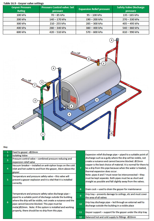
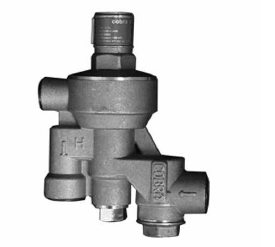
Pressure Control Valve (PCV)
The Pressure Control Valve or Pressure Reducing Valve only has one function and that is to reduce the mains pressure to a constant working pressure. If the pressure rises downstream due to any reason it cannot rectify the system pressure. Pressure control valves are of the pressure balanced type, which means that the set pressure (outlet) is unaffected by changes in the supply pressure (inlet) i.e. the set pressure to the geyser will remain constant.
The PCV is normally installed in an incoming water mains line, before it enters the building. The PCV ensures that the system is not over-pressurised by high pressure spikes or surges, which would cause water wastage through full discharge from the geyser safety valves if no pressure control valves were fitted and any other potential damage to the various fittings in the distribution system which could have a lesser pressure rating.
Many PCV’s have the added advantage of acting as a strainer to the water distribution system of dwellings; when they are fitted with a strainer/filter which eliminates sediment, dirt and unwanted particles into the water system. (This is a removable part that can be cleaned and serviced).
Expansion relief is combined in the pressure control valve; during the heating cycle water will expand and increase in its volume. As water is not compressible an increase in pressure takes place. This increased pressure is released through the expansion relief valve.
The formula to calculate the correct amount of water that will expand is:
H – C x L x 0.0004
Where:
H = How hot the water is heated
C = How cold the water is before heating
L = How many litres are heated during that heating cycle – not the capacity of the cylinder.
0.0004 = The expansion coefficient of water
The expanded water volume can be as high as 4% of the volume of heated water. It is important to remember that the expansion relief drain pipe is normally a “wet” pipe because it will discharge or drip a number of times a day (whenever reasonable amounts of hot water is drawn the geyser has to reheat).
The discharge expansion relief pipe should always be visible, as it is an extremely important indicator that there is either a valve failure (expansion or pressure reducing) or a fault in the system, should water be discharged under pressure or a constant flow. It is also recommended to make sure that this pipe discharges where it will not be a nuisance.
Note: It is very important that the discharge pipes from the expansion relief and from the safety valve never be joined together.
Guidelines for the maximum distance from the water heater (geyser) to the pressure control valve are recommended as follows;
- 400 kPa system 15m
- 600 kPa system 30m
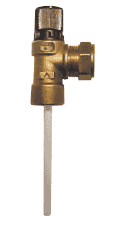
Temperature and pressure safety valve (TPS or T&P)
The function of this valve is to protect the hot water cylinder from over-pressurizing when the water in the cylinder is heated. When the pressure inside the hot water cylinder rises, due to the heating process, the pressure valve would open should the pressure inside the cylinder exceed the set pressure of the pressure safety valve. The safety valve is designed to release water if the pressure in the system exceeds 1.5 times the rated working pressure, i.e. 900 kPa for a 600kPa geyser – See Table 16.9 above.
It is also set to release if the temperature exceeds 98°C. An over temperature condition is normally as a result of thermostat failure.
- The safety valve will discharge over heated water until it senses that the water has sufficiently cooled and then close. This process will continue until the over temperature condition is rectified.
- In an over pressure condition the safety valve will discharge continuously until the source of over pressure is eliminated.
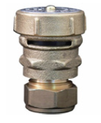
Vacuum Control valves
In closed systems and in valve operated vented systems, vacuum control valves shall be installed on both hot and cold water pipes to and from the geyser to ensure that both lines and the water heater are vented and that siphonage is prevented. The idea is that if there is any reverse flow in the supply to the geyser, the vacuum breaker should immediately open and let air into the pipeline, allowing the column of cold water to run backward without allowing the hot water to siphon up the inlet pipe, out of the geyser. So while the water in the cold supply Pipes could run backwards, the hot water remains safely at rest in the geyser where it belongs. That is why this height of the anti-syphon loop should never be lower than the top of the tank in the geyser.
Thermostat
The thermostat will cut out and the reset button will activate if the following conditions prevail:
- The temperature of the water is in excess of 104° C.
- Power surges or fluctuations which exceeds specified amperage of 20 amps.
- Inadequate electrical connections.
- Installation of elements which exceed the capacity of the 20 amp thermostat.
- Recommended operating temperature is 65° C.
Note: When replacing a thermostat the safety valve should be replaced at the same time if it has discharged.
Solar
Solar hot water systems use sunlight to heat water. South Africa has the ideal climate for solar energy and experiences some of the highest levels of solar radiation in the world.
On average about 40% to 45% of electricity used in South African homes is for water heating, using the traditional ‘electric geyser’. However, the National Building Regulation for energy usage in buildings SANS 10400 Part XA as described earlier require that 50% by volume of the annual average hot water heating requirement shall be provided by means other than electric resistance heating or fossil fuels, of which solar is one of the alternatives.
The most common types of solar water heaters used are evacuated tube collectors and glazed flat plate collectors generally used for domestic hot water systems; and unglazed plastic collectors used mainly to heat swimming pools.
Solar water heaters make use of two natural phenomena for their operation: Black objects absorb heat and hot water rises.
A solar water heater system is typically a combination of:
- A solar collector; also called a solar panel, which is an energy conversion device that absorbs solar radiation and transfers the energy to the working fluid passing through the collector.
- A water storage cylinder; solar geysers come in standard sizes similar to that of conventional electric geysers (although usually bigger). Some are non-pressure systems referred to as an open-loop, gravity fed systems relying on the thermosyphon phenomenon, while others are pressurised from 100kPa to 1000kPa depending on the circulation method specified.
In an indirect system where a heat transfer fluid is used the cylinder is normally designed with a dual purpose; one as the hot water cylinder (HWC) and the other as a heat exchanger, where the heat transfer fluid (HTF) is passed through the heat exchanger, separating the drinking (potable) water from the circulating HTF. This type of cylinder is commonly known as a ‘double jacketed’ solar HWC.
- The energy transfer medium is either water or a mix of water and a heat transfer fluid (HTF); which is an antifreeze and a corrosion inhibitor.
- A circulating pump is used in a solar hot water system where the storage tank is below the collectors; the pump is used to bring the hot water down from the collectors. These are in turn connected to controllers that switch the pump on and off controlling the water temperature in the cylinder and collectors.
Orientation and inclination of Solar Heat collectors
Correct collector orientation and inclination is imperative when installing a solar water system. These two angles will affect the overall performance and efficiency of the solar hot water system.
Whenever possible collectors should face true north in the Southern hemisphere; If the collector cannot be installed facing north, an orientation facing slightly west is more advantageous than east, due to higher ambient temperatures in the afternoon. A deviation of 45° east or west will have no major effect on the collector efficiency. However deviations greater than this will require extra square meters of collectors to compensate for solar losses.
The rule of thumb for pitching the collectors is latitude +10°. This will give more of a uniform solar collection from month to month. In summer, energy collection is reduced due to high solar reflection, and in winter when the sun is lower on the horizon, the maximum energy is captured. However with an efficient collector, variation of performance is relatively insensitive to collector orientation within ±50° of the northsouth line for low latitudes, but becomes more significant at high latitudes. For installations near the equator, performance is obtained for inclinations within 15° of the latitude angle.
Cape Town has latitude of 33° south and Johannesburg has latitude of 26° south. If your roof angle is within 10° of your desired angle you can mount the solar collector flush against the roof surface. If the roof pitch is not ideal, it is generally cheaper and neater to install an extra collector than use a frame to achieve the optimum performance.
The Minimum recommended angle of inclination for mounting flat plate collectors is 10°, in order that adequate thermosyphon flow occurs. It also means that rain will wash dust off the glass of the collectors more efficiently if the angle is greater.
The maximum recommended angle of inclination is 50°. Any greater angle means that with a close-coupled system, shading by the storage tank is likely at some times of the year. A further consideration, if exceeding 50° is one of aesthetics.
Shading
The solar collectors should be installed in a position that would be shade free for the whole year. As a minimum, shading should be avoided between 9am and 3 pm; this is the period that most of the solar energy is absorbed .
Partial shading of parts the collector in the early morning or late afternoon will have little effect. Shading generally would have a greater effect in winter, when the sun is lower in the sky and its path of solar intensity is lower.
If shading is unavoidable, for example, a nearby building; adding additional collectors can compensate for this. But the bottom line is if the solar hot water system is to work efficiently and effectively all year round shading needs to be avoided. Heat transfer method Solar water heaters, which heat water for personal use, are classified as either being open (direct) or closed (indirect) systems.
Open/Direct system
Open circuit systems simply circulate the (potable) water directly from the HWC through the collectors and then directly to the buildings hot water supply. This system is ideal for locations where the ambient temperature never falls below freezing and where the water quality is good. As most areas in South Africa regularly have temperatures below freezing in winter as well as regular incidence of frost, and due to the calcium content in many areas, the open/direct system is generally not considered viable. A direct system should only be used where the following conditions prevail;
- Frost free areas
- Lime free water
- A not too aggressive water/soft water to prevent long term corrosion
These systems are generally less expensive than indirect systems, as no heat exchanger is required and where the use of a heat transfer fluid is eliminated.
Closed/Indirect system
A closed/indirect system can be used in all conditions and is the most commonly used system. In a closed/indirect system the (potable) water used does not circulate through the collector panels. The agent (heat transfer fluid (HTF)), generally a glycol and water mixture, used in the collector panels is heated and that heat is then transferred indirectly through a heat exchanger, i.e. with-out coming into contact with the (potable) water, which in turn heats the (potable) water
Closed/indirect systems are popular in areas subject to extended freezing temperatures, as they offer guaranteed freeze protection. They are also used extensively in areas with hard water conditions as lime scale build up within the collectors is prevented.
Heat transfer fluid
Heat transfer fluids carry heat through solar collectors and heat exchangers to Hot water cylinders. The fluid must be a food-grade glycol solution, which is not poisonous. The glycol is usually mixed with water depending on the location in which the solar system is being installed. Manufactures specify the correct glycol/water mixing ratios. Most glycols deteriorate at very high temperatures and should be checked on a regular basis.
Pressure system
Solar water heating systems are available in both pressurised and low-pressurised systems:
Pressurised System
This system uses the water pressure of the mains.
Low-pressure System
This system is an open-loop; gravity fed system and relies on the thermosyphon phenomenon (also commonly termed as a Thermosyphon Solar Heated Water System). Warm water rises to circulate the water through the tubes to the tank. Mains water flows into the tank via a feeder tank similar to that of a toiler cistern and then to the lower part of the vacuum tubes, where it is heated. The water ascends in the tubes as it’s heated, and flows on to the tank before going to the user.
This system requires low maintenance and its high efficiency provides hot water after just a few hours of sunlight. An electrical backup system can provide energy during periods of cloudy weather.
These systems have limited use with modern plumbing systems, as they can only be used where there is a small head of pressure. One major drawback of these systems if not installed or used correctly, is they can cause serious scalding.
Circulation method
Thermosyphon
Thermosyphon
Thermosyphon systems or as some call passive systems are complete on-roof hot water systems, in which the storage tanks and solar collectors are mounted on the roof as a unit either as an integral or close coupled combination.
In a direct system the cold and hot water supply lines are connected to the domestic (potable) water system. Due to the solar irradiation and differences in the specific weight of cold and hot water, the heated water rises to the top of the collector where it flows into the storage tank and displaces the cold water in the storage tank, which in turn flows into the collector and is heated there.
The heated water then flows into the hot water lines and can be used directly for cooking, washing or showering. The advantage is that this circulation method is often the most economical solution; the technology is fool proof and requires almost no maintenance. If the sun does not shine for several days or the water consumption rate is abnormally high, the storage tank can have an electric element installed where a thermostat automatically activates the electric element.
In an indirect system the heat transfer fluid is heated in the collector, and where the ‘thermosyphon circulation phenomenon’ causes it to flow to the tank where a passive heat exchanger transfers the heat of the HTF to the (potable) water in the tank.
Pump-Circulated
In a “pump-circulated” system or active system the storage tank or HWC is usually installed in the roof or separately from the collectors and usually below the level of the collectors; a circulating pump moves water or heat transfer fluid between the tank and the collectors hence the terminology active. This pump can be electrically or solar operated.
If solar operated a photovoltaic (PV) panel is used to drive the pump in an active system, and the installation of a controller is crucial. This prevents the pump from switching on early in the morning when there is light to drive the pump but while the collector is still cold, which causes the hot water in the storage tank to be cooled.
Collector/storage combinations
Integral
Integral
An Integral water-heating system is usually an open/direct system in which the hot water storage tank is incorporated integrally with the collector and is stored in the body of the collector, which is simple, effective and inexpensive. If using an open/direct system it is only suitable in moderate climates with good sunshine and in applications where hot water is only required in the late afternoon or early evening as heat is lost overnight.
Close-coupled
In a “close-coupled” system the storage tank is normally mounted horizontally immediately above the solar collectors (as a separate component) on the same chassis on the roof and works on the thermosyphon circulation method ‘passive’ and where the heat transfer can be either a open/ direct system, or a indirect/closed system using flat plate type collectors or evacuated tube collectors If the sun does not shine for several days or the water consumption rate is abnormally high, the storage tank or hot water cylinder can be fitted with an electric element where the thermostat will automatically activate this element. This ensures that hot water is always available.
Split
Split systems typically use a pump to move the heated water or heat transfer fluid through the collectors and into the Hot Water Cylinder (HWC) and in the case of indirect systems through the heat exchanger, where the heated, pumped HTF will heat the (potable) water in the HWC. The solar collector is placed on the roof while the HWC is usually in the roof. The pump ensures transfer of fluid from the collector to the HWC.
Though this ‘active’ system has more components and is hence more expensive, its advantages are twofold:
- i. The HWC does not need to be placed directly above the collectors, allowing the designer more options of screening the collectors from view. The HWC can be placed up to 20m away from the collectors depending on the system and manufacturer used.
- ii. The system is more efficient as the pump regulates the flow rate of the water or glycol solution through the system.
If the sun does not shine for several days or the water consumption rate is abnormally high, the HWC can be fitted with an electric element where the thermostat will automatically activate this element. This ensures that hot water is always available.
Pre-heater
A pre-heater is a system in which a solar water heater does not contain a means of supplementary heating and is installed to preheat the cold (potable) water supply prior to its entry into any other type of household water heater. A pre-heater is no more effective than connecting any other solar system directly into the hot water supply and bypassing the conventional water heater. The only added advantage from a pre-heater is that there would be a larger volume of] heated water to draw from.
Collectors
Flat plate
The principle of operation is relatively simple, although there have been advances in the construction technology, materials and absorber surface that are used by different manufacturers.
All flat plate collectors have a collector box, usually fabricated from aluminium. The absorber plate, with tubes attached for heat transfer to take place, is placed within the box. Beneath the absorber plate is insulation, to prevent the loss of heat through the bottom of the box. Above the plate is a transparent cover, usually glass, which is designed to absorb solar radiation and convert it to heat in the absorber plate.
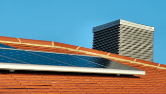
Since the surface-to-volume ratio increases sharply as the diameter of a pipe decreases, most flat plate collectors have pipes less than 1 cm in diameter, sharply increasing the efficiency of the heating process. How the water or water/ glycol (HTF) is brought into contact with the plate, also affects the efficiency of heat transfer from plate to fluid. In many flat-plate collectors the metal surface of the pipe is increased with flat metal flanges or even a large, flat metal plate to which the pipes are connected at the top and bottom of the absorber plate, to increase efficiency. The risers are in thermal contact with the absorber plate and are also sometimes referred to as ‘fin and tube’ collectors.
When the sun shines through the glass cover, solar radiation is absorbed by and heats the absorber plate. The absorber plate conducts heat to the water or HTF in the riser tubes connected to it. Through natural convection (thermosyphon) the hotter, less dense water or HTF rises to the top of the riser pipes. At the same time, the colder, denser fluid moves to the bottom, creating circulation.
Evacuated tube system
Evacuated tubes are more complex than flat plate collectors – originally developed for northern hemisphere climates, where solar radiation is relatively low. Evacuated tube collectors all have evacuated glass tubes which are connected to a header pipe that is housed in a manifold box and secured to a frame.
Evacuated tube collectors use two glass tubes, in between which a vacuum has been created. The outer glass tube and the vacuum within protect the absorbent coating and structural materials from corrosion. The absorbent coating is most often a thin layer of barium.
The evacuated tube system is rather like a thermos flask, with a vacuum in the space between the walls. The vacuum is a very effective insulator, eliminating conduction and convection. The heat arrives through the vacuum, as radiation, and is absorbed by the coating on the inner tube.
The heat from the absorbent coating is transferred to the heat conveyance system. The fluid heat conveyance is an evaporating-condensing liquid that evaporates in the collector tubes, and then transfers the latent energy (heat) to the cold water in a manifold, through condensation.
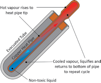
Heat transfer is always in one direction – from absorber to the manifold (thus collector to storage tank) and never the reverse.
As each tube is independent, individually damaged tubes can be replaced with-out interference to the still functioning system. Tube damage is indicated by the tubes turning white when the vacuum has been broken. Below is a schematic representation of an evacuated tube type collector. Each company has their own, usually patented, evacuated tube technology; the following figure is merely a representation to explain the concept.
There are various methods by which heat is transferred to the fluid that is to be heated using evacuated tubes; the heat pipe method is the most commonly used.
It is a sealed copper tube in the centre of the evacuated tube and an absorber fin is attached to the copper tube. The tube contains a refrigerant liquid and the internal pressure of the tube is reduced and sealed. As a result, the boiling temperature of the refrigerant liquid, in the tube, is lowered well below 100°C; depending on the pressure, it may boil at 40°C.
When the refrigerant begins to boil it forms a vapour, which fills the tube and rises rapidly to the top of the tube. The vapour flows into the condenser, which is inserted into the header. The heat created within the tube is transferred to the fluid that passes through the header. Once the heat is transferred, the refrigerant liquid is condensed (returns to liquid) and flows back down the tube where the process then repeats itself.
The header is the section within the manifold in which the water or HTF from the solar hot water cylinder passes through. The header is made from copper, which is an excellent heat conductor and is corrosion resistant. The top of the evacuated tube heads come into contact with the header.
Sizing
System sizing is not the same when compared to a conventional electric hot water cylinders. Correct sizing of solar water systems is imperative for maximum savings. The size of the system involves the sizing of two components:
- The hot water storage tank, and
- The collector area or number of collectors
The first calculation that needs to be assessed is the number of litres of hot water required for daily use. This will vary enormously from family to family, but a rule of thumb of 50 to 80 litres of hot water per person per day would assist in your assessment.
A rough rule of thumb for collector size (area), is 1m² of collector per person, plus 1m² for each major appliance using hot water, for example a dishwasher.
Standards
The plumbing installation of a solar water heater is no different to that of a conventional geyser and therefore SANS 10254 “code of practice” still applies. Added to this; solar water heaters are regulated by the following standards:
- SANS 10106: Solar water heaters
- SANS 1307: Domestic solar water heaters
- SANS 204: Energy efficiency in buildings
- SANS 10400: Application of the National Building Regulations
- Part XA: Energy Usage in Building
Extract from SANS 1307: 2009
4.1 Types
A solar water heating system shall be one of the following as shown in Table 16.10
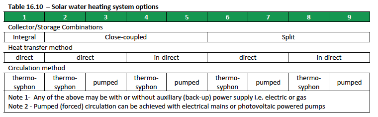
Costing
The calculation of long term cost and payback periods for Solar Water Heating (SWH) Systems depends on a number of factors; some of these are:
Price of purchasing solar water heater (more complex systems are more expensive)
- Efficiency of system purchased
- Installation cost
- State or government subsidy for installation of a solar water heater
- Price of electricity per kW.h
- Number of kW.h of electricity used per month by a household
Heat pumps
A heat pump is a ‘machine operating on a reversed heat engine cycle to produce a heating effect’. Energy from a low temperature source (e.g. earth) is absorbed by the working fluid, which is mechanically compressed, resulting in a temperature increase. The high temperature energy is transferred in a ‘heat exchanger’. The operation of a heat pump has been likened to that of a refrigerator, though saving and using the heat instead of throwing it away. Most applications have achieved a coefficient of performance (COP) of around 3; that is to say, the output is something like three times as great as the input.
A technology that is simple and effective in lowering electricity consumption is the heat pump. Heat pumps offer households and commerce and industry an opportunity to reduce water heating costs significantly.
A heat pump can save up to 67% of the energy used to heat a tank of water, compared to a conventional electrode heater.
Heat pumps use the reverse cycle of a refrigeration plant to heat air or water. The heat pump system uses an evaporator, a condenser, a compressor, refrigerant gas and an expansion valve within a closed circuit. It may seem strange that an electro-mechanical device with moving parts – a motor driving a compressor – can be more efficient in heating water than a typical resistance-element geyser. In fact, a heat pump can be three or four times more efficient.
Gas
Gas Water Heaters (GWH) have been called many different names in the past; gas geysers, instant water heaters, pushthrough geysers, tankless water heaters etc. These units have been around for decades and are the preferred method of efficiently heating water around the world. Why – because they heat water on demand, only as you turn on the hot tap will the unit start to produce hot water, meaning extremely high efficiency and very little heat loss.
GWH’s are measured by the ‘flow rate’ of hot water they can deliver. The older traditional GWH’s provided between 11-18 l/m, enough for single use (1 tap at a time). Modern GWH units come in 20 & 26 l/m which allow for multi-point use (dependent on climate) with up to 3 taps/showers used at any one time.
Over the years, GWH’s have developed enormously; gone are the days of running outside to relight gas geysers, also gone are the days of lukewarm and weak showers, with cries from the cold water coming through after someone else opens another hot tap while you shower.
Why Use Gas Water Heating
- Unlimited hot water (as long as you have gas)
- No hot water is stored (heating on demand)
- Low maintenance, Low capital outlay
- Can pay for itself in 8-10 months (LPG Installation) or 4-6 months (Natural Gas Installation)
- Can be retrofitted to current hot water OR SOLAR systems
- Cost savings in 3 forms;
- 1. Pay as you use hot water
- 2. No storage of hot water,
- 3. Lower cost of heating water with gas
LPG (Liquid Petroleum Gas)
LPG is a by-product of the oil refining process and is abundantly available throughout South Africa and the Continent. The use of tankless systems can create 30-50% savings on energy costs, as well as reducing ones carbon footprint immensely, as water is only heated as it is being used. LPG (and more so Natural Gas) combusted gases are also far less damaging to the environment than using energy produced by coal fired electric plants.
Natural Gas
Natural gas is a fossil fuel primarily made up of methane (85%) and when burned, gives off energy. Unlike other fossil fuels it is extremely clean burning and emits lower levels of harmful byproducts into the air. Egoli Gas provides Natural Gas in the Greater Johannesburg area, piped directly from Gas Fields in Mozambique. For those lucky enough to be using Natural Gas, savings of up to 50% can be achieved on identical appliances running on LPG.
Why Gas Water Heaters?
GWH units are compact, easy to install, contain integrated diagnostic software for easy maintenance, GWH’s can also be added to existing hot water, solar or heat pump systems to further reduce electrical usage. Units can be expanded using the ‘EZ Link’ link if greater water capacity is demanded. As more hot water taps are utilised, the ‘EZ Link’ will recognize this and request the next unit to ignite and supply hot water. GWH’s can operate on all modern taps, flow restrictors, water savings devices and almost any plumbing systems and are available for use with LPG or Natural Gas.
Safety & Installation
All gas installations must be carried out by a registered gas fitter, accordingly to SANS10087. A typical LPG installation would require 2 x 48kg cylinders with a changeover regulator connected directly to the GWH. GWH are designed for outdoor use only, no additional flues etc. are required. Some units depending on make require a standard 15 amp 3-pin electrical plug for the electronics and software.
LPG and Natural Gas are colourless, odourless and non-toxic. Many units are supplied with an additive odorant to assist detection by smell.
For more information on the safety of LPG contact: www.lpgas.co.za
For Natural Gas information visit: www.egoligas.co.za
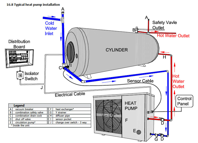
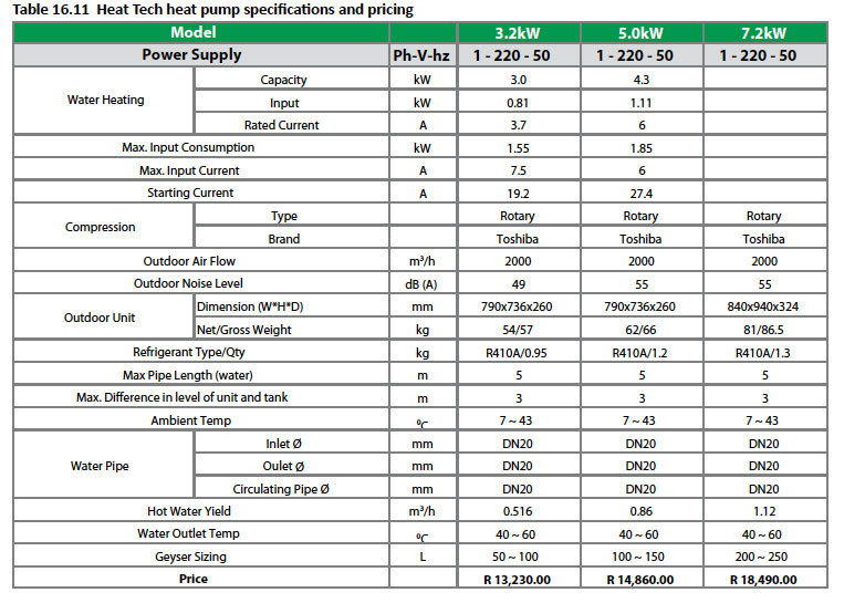
Standards
Most domestic LPG installations use a number of gas cylinders to hold their gas requirement. It is legal to have inside a house a maximum of 19Kg of gas and in a flat a maximum of 9Kg Most homes will utilize a number of 48Kg cylinders located in a freely ventilated area outside the home. It is safer than having cylinders inside the home plus the larger capacity cylinders also mean less changing of bottles giving greater convenience to the user.
48Kg cylinders are not filled at the point of use. Most consumers will use a home delivery service to deliver full 48Kg bottles to their home and to remove the empties. Should more than 100Kg of LPG be located at one residence the location of bottles and installation of the gas lines needs to be approved by the local Fire Prevention Authority.
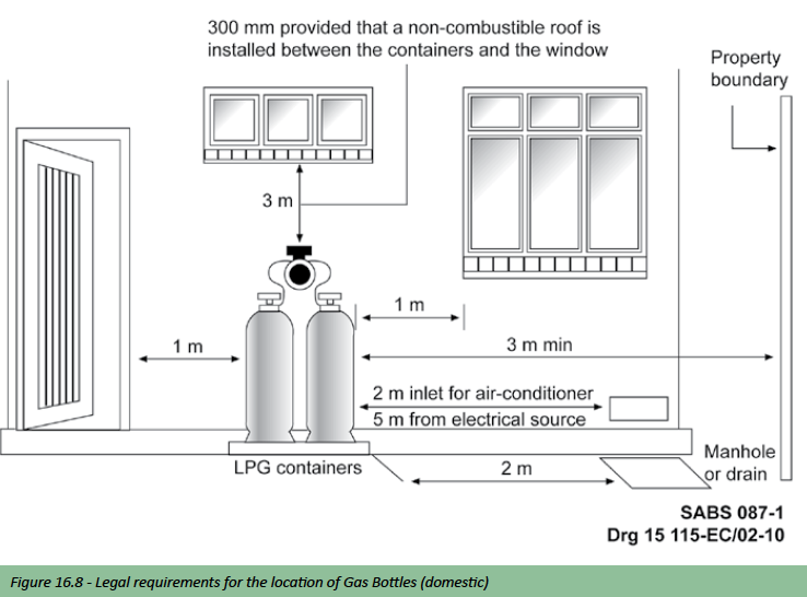
Sanitaryware and other fittings
Plumbing fittings and Sanitaryware should be efficient, strong, durable, impervious to water and corrosion resistant. The fixture/appliance or fitting should be user friendly (of particular importance to the physically disabled); and they should also be hygienic i.e. easy to clean and functional.
User choice is typically influenced first by cost, followed by appearance then availability; seldom is the choice for functional reasons or practical reasons like: Spares availability, product warranty, water consumption and technical support considered.
Examples of fittings illustrated in this section represent only a limited selection of the wide product range available. Further detail of product specifications, range and scope is contained in product literature available through manufacturers, Sanitaryware merchants and Massbuild stores. A visit to an established merchant or supplier should be enlightening as an indication of what products are available.
Note: Sizes of normally installed fittings/appliances are provided in the following sections (where applicable).
Taps and mixers
Taps and mixers including stop valves must be leak proof when closed, and they should control and deliver water in adequate quantities, at not more than a specified noise level, over their full design lives. Taps and mixers should be comfortable to use and easy to operate. All water pressure to mixing points MUST be balanced and the flow pressure should not vary by more than 20%.
In most respects, taps and mixers with ceramic discs (cartridges) are superior to the traditional designs, being far less prone to leakage. Their operating characteristics are different, requiring, for instance, less rotation of the spindle from open to closed positions than the screw-down type with conventional rubber or plastic washers.
Ceramic disc taps and mixers should ideally be used in higher operating pressure systems Strainers should also be used in the water distribution system to prevent dirt and grit into the system. By law all installations must be protected from the ingress of dirt; it is not only good plumbing practice but a must.
It is important to consider the minimum rates of flow (see water supply above) when choosing which type or style of tap or mixer one will use at a specific point; i.e. using certain 15mm fittings at a bath will not provide the optimum rate of flow.
Another important consideration is the style of tap and its purpose; the operating part be it a handle, lever or knob (the shape) should permit sufficient torque to be applied to the spindle to open or close the tap, without discomfort to the wet, soapy hand of an operator; e.g. a lever type or cross head part to a sink mixer is more practical than a smooth knob.
Mixers and taps are typically made from brass which is a metal alloy made from a mixture of copper and zinc, often with smaller amounts of nickel, lead, iron, etc. added to this mixture; the brass used should be dezincification resistant. Once the brass castings have been moulded they are then machined, polished, and plated to suit different types of finishes; e.g. Chrome Plated.
It is also important to remember that many valves or mixers are actually built into the wall at the same time the water distribution system is installed and for this reason the choice and make of these fitting needs to be specified well before the actual building starts.
It would be impossible to illustrate the wide range of taps and mixers that are available in this publication. We have tried to provide sufficient generic information to guide the reader in what choice would best suit your needs and application. One must also be mindful of the fact that with this large variety of choice; the variation in quality and price is as varied.
Appropriate standards which incorporate test criteria include the following;
- SANS 226: Water taps (metallic bodies) – (Type1) – Heavy Pattern; (Type 2) – Light Pattern (BS 1010) ( BS 5412)
- SANS 1480: single control mixer taps (BS EN 1286)
- SANS 1808-9: Water supply and distribution system components Part 9; metering taps and valves (metallic bodies)
This can also include SABS/ISO9001 and JASWIC approval. Some important Abbreviations when reading about technical specifications on taps and mixers;
- ISO – International Standards Organization
- JASWIC – Joint Acceptance Scheme for Water-Services
- BSI – British Standards Institute (BS)
- DZR – Dezincification Resistance (Brass)
Installation Components
Manufacturers and suppliers of taps and mixers usually have numerous ranges available; from the standard day to day budget ranges to luxury designer ranges.
Bath spouts
Bath spouts are available as wall mounted or deck mounted (Pillar type); as plain spouts and as diverter spouts, to allow for a shower attachment. Also available are combi-fillers (Aquafill or Nikki) which are installed into the overflow of the bath and act as a combination filler and overflow. Bath spouts are usually installed after the tiling; unless you are using a Nikki spout which is fitted at the time the bath is built in.
Shower arms
Shower arms are available in numerous shapes and sizes and are installed after tiling.
Valves
Valves described here are fittings which either stop the flow of water through a pipe or regulate the flow. Pressure control valves, temperature and pressure safety valves and vacuum control valves have been discussed above under Hot water systems. Thus valves used for the control of water flow can be described in the following categories:
- Gate valve – valve with a sliding disk which opens to the full pipe bore.
- Stopvalve/stoptap – a fitting that stops the flow of water or regulates water flow in a pipe; also referred to as a shut off valve or isolating valve. Undertile stopcocks or as some call side valves are classed as stopvalves or shut off valves. One-way stopvalves (typically undertile stopcocks) have an arrow showing the direction of flow on the brass body of the valve.
- Stopcocks – a fitting typically externally operated, which turn off a water supply and allow the flow of water in one direction only and prevent backflow from the building and possible pollution of the mains; usually the property of the local water utility.
- Flush valve – a flushing valve supplies a precise quantity of water to flush a WC, where no cistern is used. It has the advantage of not having to wait while the cistern refills.
- Float valve – also known as a ball valve is a float operated valve used to control the flow of water into a water reservoir or tank, typically a WC cistern.
- Check valve – a non-return valve fitted in a water supply line to prevent backflow; available as swing type or spring loaded.
- Angle valve – is a screw down valve with its outlet at right angles to the water supply pipe, normally used to isolate water supply to cisterns and mixers. They are typically supplied with a riser pipe and can also be connected by use of a flexible connecting pipe.
- In line strainer – Although this is not a valve it is normally associated with valves. Strainers are used to prevent dirt and grit entering the water distribution system from the mains.
See below for figures illustrating these valves
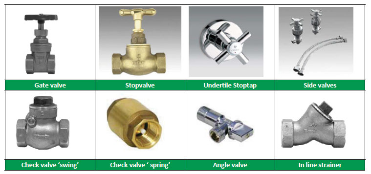
Sinks
A single sink in a dwelling should be large enough to take an oven shelf, or the largest object commonly washed there, and therefore the bowl should be around 400 mm × 340 mm × 170mm deep. Double bowl sinks usually have two equal bowls about 370 mm × 340 mm, but a more useful combination might be one large bowl (say 500 mm × 340 mm and 170 mm deep) big enough for cleaning oven trays and, if necessary, washing clothes and household linen, and a smaller rinsing bowl alongside.
A removable rack may be provided over the rinsing bowl so that dishes can be stacked on it and sprayed with hot water, but if this is to be done the bowl should be at least 400 mm × 350 mm.
Whichever type is chosen, it will be useful if there is a waste outlet large enough for a waste disposal unit to be fitted later without major alterations. A basket strainer waste will trap food scraps before they clog up the pipe. Where unequal bowls are being used, this outlet should be fitted to the smaller bowl.
How to install an inset sink
Tools required
- pencil
- jigsaw
- flashlight
- paint brush
- tape measure
- silicone sealant
- resin and hardener
- drill – 9mm or larger
- nut driver – 9mm (3/8)”
- screwdriver – shank at least 152mm(6″)

Step 1
Trace the cut out template onto the work top. The template is included in the packaging as a perforated tear out.

Step 2
Drill holes into work top at each corner of the marked area to allow for easy cutting of the MDF
Step 3
Follow the lines of the template and cut worktop with a jigsaw.

Step 4
To ensure that the worktop is water resistant, seal inside edge of cut out with a resin and hardener compound.
Step 5
Allow to dry until the compound forms a silicone like surface on the cut area to prevent swelling of the MDF in the event of water seepage.
Step 6
Fix clips to sink. Ensure there are a minimum of 4 clips on either length side of the sink.

Step 7
Remove screws from each clip so that the sink will fit perfectly into the cut out. These screws will then be re-attached to the sink clip, working from the underside of the work top.
Step 8
Generously apply silicone onto folded edge of sink and along the edge of the cut out. Silicone acts as glue and further prevents water seeping underneath the work top.
Step 9
Place sink onto work top.
Step 10
Attach screws to clips and tighten to its maximum tension. The tightening ensures that the sink is pulled down firmly onto the work top preventing the sink from lifting at the edges and bowing.
Step 11
Wipe away oozing silicone from the work top and smooth out edges.
Step 12
Allow to set for 24 hours.
Even though dishwashers have become increasingly popular over the years as a more hygienic, more efficient option than washing up by hand, people still spend two thirds of their time in the kitchen at the sink.
Types
- Inset sinks – have a flush rim at the counter surface; also referred to as a drop in sink.
- Undermount sinks – fitted to the underside of the counter after cutting out the shape of the bowl required in the counter.
- Sit on sinks – fitted above the counter, and have a raised rim.
- Prep bowls – usually round bowls which are typically of the inset and Undermount type.
- Butler – typically ceramic; a sink on a lowered counter top
Materials
Stainless steel
Essentially, stainless steel is a low carbon steel containing chromium at 10% or more by weight. The addition of chromium gives the steel its unique stainless, corrosion resistant properties; tough and hard wearing. Stainless steel is an alloy steel with varying amounts of alloying metals, typically chromium and nickel 18% Cr. and 10% Ni. (Hence the terminology 18/10 stainless steel) and available in different grades:
- Grade 304; is the most commonly specified austenitic (chromium-nickel stainless class) stainless steel, accounting for more than half of the stainless steel produced in the world. This grade withstands ordinary corrosion in architecture and resists most chemicals. Grade 304 is available in virtually all product forms and finishes. It has excellent forming and welding properties.
- Grade 316; austenitic (chromium-nickel stainless class) stainless steel containing 2% – 3% molybdenum (whereas 304 has none). The inclusion of molybdenum gives 316 greater resistance to various forms of deterioration.
Lower alloy grades (303 & 304) resist corrosion in atmospheric and pure water environments, while high-alloyed grades (316) can resist corrosion in most acids, alkaline solutions, and chlorine bearing environments.
Stainless steel products are regulated by the following standard;
- SANS 242: Stainless steel sinks with draining boards (for domestic use)
Ceramic fireclay sink
Ceramic sinks or more commonly referred to as butler sinks are acid and alkali proof and the high gloss enamel finish makes them easy to clean. Ceramic sinks are made from enameled fireclay; a mixture of heavy clays coated with white enamel to give a heavy, robust product which is resistant to most conditions in use.
Combinations
- Single end
- Double end
- Corner
- Double centre
- Centre
Sanitaryware
Baths
Baths are manufactured from a variety of materials, in different styles, shapes, sizes and colours with white being the most commonly used. Very briefly below we describe these categories.
Material types
Acrylic – The majority of baths installed today are acrylics which have the following benefits:
- nice and warm to touch
- naturally non-slip
- matching of all ceramic colours
- improved thermal resistance
- light weight- easy to install and transport
- easy transformation / design
- excellent surface gloss / colour accuracy
Pressed steel baths – Steel baths are stiffened by pressing the sheet into the profile of a bath giving it regular longitudinal folds providing the necessary strength and stability. The baths are then enameled and baked providing a very hard durable smooth surface.
Cast Iron baths – Cast Iron baths are shaped or cast in moulds. The baths are then enameled and baked providing a very hard durable smooth surface. These baths are popular in the free standing shapes although very heavy and the most expensive.
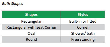
Providing or determining the positions of wastes for baths is very important when specifying the bath and providing the correct detail to the plumber and installer of the bath as to where this important waste will be fitted. It can also be a functional decision where one doesn’t have to hang over the bath or climb into the bath as such to put the plug in.
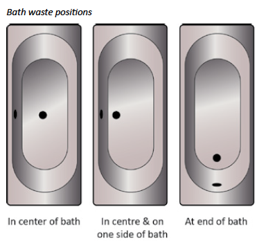
Dimensions
Standard baths are usually available in two lengths – 1700 and 1800mm – with widths of 800, 750 and 700mm. Heights of baths differ from 395 to 525mm for built in baths and from 460 to 665mm for freestanding baths. Other lengths include 1400, 1500, 1600, and 1900mm with widths of up to 900mm.
Bath accessories
- Baths are available with or without handles depending on type and needs to be specified.
- Freestanding baths are available with fitted full surround or side only polished stainless steel towel rails and a variety of feet.
- Some baths can be jetted to become mini spa baths.
- Some baths are available with pre-manufactured side panels.
Water Closets
Water closets (WC’s) are commonly referred to as toilets; which is incorrect as the toilet is the actual room itself or as defined in the Oxford dictionary; toilet = 1] lavatory. 2] Process of washing oneself, dressing, etc. (at one’s toilet).
The following is offered to clarify terminology further:
- A WC pan is also known as a WC bowl to some; we refer to it as a pan.
- WC pans can also be referred to as pedestals; we again refer to them as pans
Types of WC Suites
WC suites are generally described in terms of the cistern position:
- Close Coupled – the underside of the cistern rests directly on the back of the WC pan. This configuration is the more popular in domestic applications as it is aesthetically pleasing and with its low overall height it can be screened off easily and used below windows.
- Low level – the cistern is fixed on the wall immediately above and behind the WC pan and connected by means of a metal or plastic flushpipe.
- High level – the cistern is high above the WC pan and is connected to the pan by means of a long flushpipe. The cistern is typically flushed by means of a chain pull attached to the side of the cistern. This configuration is seldom used today.
- Concealed or ducted – this configuration is becoming very popular, where the cistern is concealed behind the WC pan in the wall or dry wall; with the actuator (the flushing mechanism) being the only visible item. WC pans fix back-towall, either floor mounted or wall hung, which can include being fixed to a frame which is part of the concealed cistern.
- Flush valve – this system is where no cistern is required, the flush occurs when a button on the flush valve is pushed which then delivers a pre-determined volume of mains water at high pressure through the flushpipe into the WC pan. This system is seldom used in domestic applications and only used in commercial application like shopping centres and hotels.
WC Pans
Wash-down pans are the most common type of flushing systems available – water cascades into the sump of the pan and forces waste material through the trap into the drainage system.
The WC pan has a rim which allows the delivery of water into the pan (wash-down) in the correct way to both flush the sump and to clean the sides. Most WC pans normally specified have an open rim allowing water to be carried to the front of the pan and for the wash-down to circulate around the inside of the pan.
Also available are closed or boxed rim types – the rim is formed in the manufacturing process as a tube with a number of holes punched in its underside to deliver water in a predetermined pattern allowing the wash-down around the sides of the pan, this type is more hygienic, creates the least turbulence and is the quietest in operation; but more expensive.
Also available are rimless pans but they are seldom used in domestic applications.
WC pans are available with one of two trap configurations, ‘S’ and ‘P’; the ‘P’ type or the horizontal outlet type has been preferred in recent times. With suitable connections, it can be converted to an ‘S’ outlet and a wide variety of other layouts is possible.
WC pan Installation
WC pans can be floor mounted or wall mounted and with other types like the squat pan fitted at floor level. Screws (which are recommended) can be used on most floor mounted pans available today to fix the fitting to the floor, making installation, repair or replacement a simpler process.
Note: Generally the use of cement mortar mix is not recommended for fixing WC pans and if used the mix should be weaker than 6:1 sand/cement and without any additives.
WC Cisterns
The most common size of cisterns is 6 litres and 9 litres, depending upon the manufacturer and design. Cisterns are available as a single-flush type or as a dual-flush type; the dual-flush being more economical in respect of water consumption. Dual-flush cisterns allow for two kinds of flush, a half flush and a full flush; the half flush is used to dispose of liquid waste and the full flush to remove solid waste from the pan. This can be referred to as a 6/3 or 9/4.5 cistern i.e. 6 litres for full flush or 3 litres for dual flush.
Dual-flush cisterns are expected to become mandatory. Smaller capacity cisterns (e.g. as low as 4 litres) are expected to become more common in the future. The flushing mechanism can be on top (push button) or in some instances on the front of the cistern (pull handle or knob); top flush cisterns being the more popular. When the mechanism is operated a seal is lifted from a hole leading directly from the cistern into the flush-pipe or WC releasing the water into the pan. Cistern inlets are normally at the bottom or side, it is important to specify or consider this when deciding on a WC suite and to specify this to the plumber or installer as a bottom inlet cistern can mean a lower connection point for the actual water point.
Material types
Ceramic or Vitreous china – Ceramic WC’s are the most common and are formed from a mixture of china clays, ball clays and finely ground materials, which when fired produce an impervious ceramic material. Vitreous china is available with a white or coloured glazed surface. The glaze is integral with the ceramic body (Similar to that of china dinner plate) and is resistant to water absorption, burning, stains, scratching and attack by acids or alkalis.
Stainless steel – Stainless steel WC’s are ideal for many applications from high traffic/ intensive use areas to those at risk of vandalism. Stainless steel fixtures also provide innovative style to suit various types of interior décor. Plastics – Plastic or polyethylene is used in the manufacture of WC pans and cisterns which are typically used in vandal proof applications or for temporary site toilets.
Dimensions
There are no standard sizes as such for WC suites or pans; however an average depth of 700mm and width of 500mm would be adequate for planning purposes the height of a pan alone can average 400mm and a close couple suite averages 800mm in height. An activity space of 800 mm wide 600 mm deep is needed, and to full ceiling height to allow standing use. Where WCs are installed in buildings used by the public the size of the activity space in WC compartments needs to be larger than normal.
There is no significant difference in the space requirements of cistern flushed WCs and that of valve flushed or concealed or ducted WCs; although the cistern shape and configuration may be different.
Space requirements for installations for disabled persons are covered in SANS 10400: The Application of the National Building Regulations.
Accessories
Toilet seats are available in Plastic – Luxury – heavy duty – standard and in wood in various wood types and painted. Pull handles and actuators for cisterns are available in a number of different finishes depending on the manufacturer and type chosen.
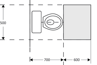
Basins
Today the range of washbasins available is so vast with varying applications from, appearance, space, function, that it is almost impossible to describe. We will however attempt to provide some basic information that will help choose the right basin.
The following is offered to clarify terminology further:
- Basins are often referred to as either a Wash Hand Basin or a washbasin.
- The common abbreviation for a Wash Hand basin is WHB.
Types of wash hand basins
Pedestal Basins – coordinating ceramic pedestals are used to screen waste fittings, water pipes and traps and support the weight of the basin. Usually the basin is secured to the wall and the pedestal to the floor using screws.
Wall hung or semi-pedestal basins – these are for fixing to the wall with the trap either exposed, or concealed by a semipedestal. Countertop basins – these are the most popular today and available in different fixing methods:
- Vessel or counter basins – where the basin is fitted above the countertop. The basin rim is typically sealed to the flat surface, using silicone sealant. And no mechanical fixings are necessary. The waste, trap and water pipe fittings are either exposed using decorative chrome plated fittings or concealed in a vanity cupboard or other fixtures which are available.
- Drop in basins – where the basin drops into a cut out in the countertop and is sealed with silicone sealant. These basins are typically used in unexposed applications i.e. with a vanity unit, concealing the fittings and service pipes.
- Under-counter or Underslung basins – A cut- out to match the inner bowl shape is made in the countertop and the basin is clipped to the underside of the countertop. Primarily used for countertops of real marble, porcelain, granite or any other water-impervious material. The waste, trap and water pipe fittings are either exposed using decorative chrome plated fittings or concealed in a vanity cupboard or other fixtures which are available.
- Semi-recessed basins – the basin fits part way into the countertop, leaving the front of the basin projecting. Suitable for all types of standard countertop materials.
Other basins – these include cloakroom basins, corner basins etc.
Shapes
Shapes of basins are designed around the basic shapes, being; round, rectangular, square, and oblong and combinations of these four.
Material types
Ceramic or Vitreous china
Ceramic wash basin are the most common and are available with a white or coloured glazed surface. The glaze is integral with the ceramic body (Similar to that of china dinner plate) and is resistant to water absorption, burning, stains, scratching and attack by acids or alkalis.
Fireclay/Terracotta
These decorative basins are usually countertop round basins which are available from various arts and craft markets and can be made to order.
Natural stone
Available in numerous different natural stone types like Travertine and Ophelia; with some standard basin types or individually cut by hand and polished by skilled artisans.
Glass
Manufactured from natural glass and available in different colours.
Stainless steel
Tough and hard wearing, Stainless steel is ideal for many applications from high traffic/ intensive use areas to those at risk of vandalism. Stainless steel fixtures also provide innovative style to suit various types of interior décor.
Composites
Composite basins Include materials like, acrylic resins and marble chip and acrylic resins and natural minerals.

Dimensions
Wash hand basin dimensions are to vast to generalize, however the front rim height is usually 800 mm for pedestal sets. Ideally, the basin needs to be fixed at a lower height for washing face and hair than for hand rinsing. The 800 mm height is really a compromise for domestic applications. Where the basin is more likely to be used by adults, a height of 900 mm may be acceptable. For small children a height of 800 mm will be difficult to reach. This inconvenience is normally solved either by adult assistance or by the child standing on a firm support.
Bidets
A bidet is essentially a low height washbasin designed for washing the genitor-urinary area without the need for full bathing or showering. Bidets are of particular benefit to people who need to wash frequently due to problems such as incontinence, and to elderly people for whom bathing is difficult.
Most bidets can be filled from taps fitted to the rim, but some are fitted with an upward spray to which special regulations may apply depending upon the local authority; it is therefore suggested advice should be sought from the appropriate authorities. The discharge is waste water not soil water, and is usually connected to a 50mm waste using a bottle trap. Many bidets are manufactured in ranges or patterns to coordinate with the WC suites being used, which can include the washbasins.
Urinals
Urinals are available in either bowl format as an individual fitting with its own flush and waste outlet, or in a slab format where the wall is lined with a multi-use urinal; commonly referred to as a continuous trough type urinal, which can differ in length from as little as 600mm to 3000mm plus and typically manufactured from stainless steel.
Urinals are seldom used in domestic applications and we have therefore not provided any products specifications or guidelines.
Shower Trays
Basic shower floor trays either set into or standing on the floor plane, and which can be fitted with various types of screening are available in the following common basic plan sizes; 800 mm × 800 mm and 900 mm × 900 mm. A tray height of 150 mm is considered to be a practical minimum and 65mm heights are available on order.
Did you know?
Since 1963 (the year CDA [Copper Development Assoc] was established)in the United States, more than 28 billion feet or about 5.3 million miles of copper plumbing tube has been installed in U.S. buildings. That’s equivalent to a coil wrapping around the Earth more than 200 times. The current installation rate now exceeds a billion feet per year.
Bathroom accessories
The bathroom accessories that we refer to here are the towel rails, toilet roll holders etc. And more often than not these fittings are forgotten and only considered as an afterthought.
Available in a number of ranges that service the entire market from the budget ranges all the way up to the luxury ranges. Manufacturers also market various other add-on accessories such as stainless steel shower caddies, racks, extension mirrors, etc.
Most accessories are manufactured from brass and are then plated usually in chrome; some ranges are manufactured from zinc alloys or aluminium. Some other variations are also available depending on the range and manufacturer – some of which are powder coated.
- Satin chrome
- Chrome/satin chrome
- Chrome/white
- Chrome gold
- White gold
Typical bathroom accessory types and variations
- Single towel rail
- Double towel rail
- Towel ring
- Toilet roll holder
- Spare toilet roll holder
- Hand towel holder
- Toothbrush holder
- Glass shelf
- Tumble holder
- Toothbrush tumbler combination
- Soap dish
- Soap rack
- Combination soap dish/hand towel holder
- Robe hook
- Double robe hook
- Mirror holders
- Shower footrest
- Towel Rack
- Toilet brush set
- Grab rail
Storm Water Disposal
Stormwater disposal in becoming a very important part of the planning process and looking after our built environment. With many local authorities requiring a stormwater plan showing what provisions and interventions are included to control stormwater especially with new developments.
Note: Stormwater control means the control of the rate and volume of stormwater released from a development site or site, and includes attenuation, detention and retention facilities.
See Siteworks – Erosion and stormwater control and dewatering techniques for more information.
The purpose of stormwater by-laws is to manage, control and regulate the quantity, quality, flow and velocity of stormwater runoff from any property which it is proposed to develop or is in the process of being developed or is fully developed, in order to prevent or mitigate the following:
- Erosion and degradation of watercourses
- Sedimentation in ponds and watercourses
- Degradation of water quality and fish habitat, and
- Excess stormwater runoff onto a public road which may pose danger to life or property or both.
What follows in this section deals more with stormwater control from a plumbing context in a domestic application.
Rainwater disposal
A considerable quantity of rainwater falls on roofs during storms. Required practice is for roofs to fall towards gutters, either at the perimeter (if installed) or to valleys, where the water flows, via the required number of downpipes into drains. However many homes are built without gutters and downpipes; where it is at least recommended that one should consider the effects of rainwater around the perimeter of the foundations and specify other means of directing rainwater away from the building; for instance a paved apron.
Where downpipes are used they should be positioned so that they are not needlessly complicated with the layout of gully and or connections to the drains planned. Where overflow of the system may occur (typically during exceptional rainfall) on flat roofs with parapets and non-eaves gutters, the design should include an overflow or emergency outlet to reduce the risk of over spilling of rainwater into the building.
Where no downpipes are used one has to consider the ground water run-off and the ground’s characteristics and existing state of saturation, which can lead to a rise in the level of the water table. If the surface of the ground cannot tolerate more rain, the run-off will need to be disposed of by means of sumps or stormwater drains in the same way that drainage will need to be provided for run-off from paved areas. Much of the rainfall can be encouraged to percolate into the ground, through carefully designed filter strips and swales.
Rainwater gutters and fittings
Gutters
Roof gutters can be described in four specific categories:
- . Can run along the eave to collect the water
- Down a valley to drain water
- Behind a parapet or chimney to direct water
- Where one or two inverted roofs meet to drain and direct water
- They form an aesthetically pleasing look to a roof line (create a band).
- To keep the curtain of rain water from drenching one when trying to enter or exit a building
- Most importantly they protect the foundations and plinths of buildings from subsidence, rising damp and the associated damage caused by the splash back onto the walls.
Many systems that have adequately sized gutters and downpipes fail in their function because of incorrect falls, insufficient downpipes or incorrect outlet locations, incorrectly installed box gutters or conditions at the outlets causing water to back up and spillover.
A roof guttering system serves three basic purposes:
Sizing of gutters and downpipes for domestic installations has become relatively straightforward, although the design of such systems for larger buildings is rather more than a simple calculation of roof area and water load.
See Roofing – Roofing accessories – for more on Gutters and flashings.
Calcamite septic tank systems
Septic tank and Soak-away – the “Septic System”
Septic systems are used when sewage treatment plants are not accessible. (i.e where On Site Sanitation is required). They safely treat and dispose of waste-waters produced in the bathroom, kitchen, and laundry. These waste-waters may contain disease-causing germs and pollutants that must be treated to protect human health and the environment. Although septic systems are usually a permanent solution to wastewater treatment and disposal, they sometimes serve as a temporary solution until sewer lines are installed. The Septic System consists of s Septic Tank , a Soak-away Field and a suitable subsoil.
The Calcamite2 chamber SABS Certified Septic Tank
The Calcamite Two chamber Septic Tank is a watertight
Polyethylene unit ranging in size from 1000L to 30 000L. It is buried in the ground just outside the home or ablution facility. The size of the tank is legally determined by the number of bedrooms in the home or daily expected flow. (use S.A.N.S 0252 as a reference).The National Building Regulations calls for a minimum size of 1500 liters for Domestic Use. It comes supplied with a manhole lid and all connection and seals.
How does the Calcamite 2 chamber Septic Tank Work?
All of the waste-waters from the home should flow into the septic tank. Even waters from the shower, bathtub, and washing machine can contain disease-causing germs or environmental pollutants. As wastewater flows into the tank, the heavier solid materials settle to the bottom (forming a sludge layer), the lighter greases and fats float to the top (forming a scum layer), and the liquid (sewage effluent) flows out of the tank. An outlet baffle (inner chamber) prevents solids and greases from flowing out with the liquids. Our unique design draws effluent from the cleanest area of the tank and allows this to be transferred to the soak-away system through hydraulic displacement. The tank’s primary purpose is to retain the solids while releasing sewage effluent to the Soak-away. The solids which remain behind are gradually broken down by a process known as Anaerobic Digestion. Here Anaerobic Bacteria digest (consume) Waste and convert them into simpler forms. For example Protein molecules are reduced into Amino acids. Methane gas is produced as a by-product of the Anaerobic Digestion Process.
The Soak-Away
The tank is connected to the Soak-away via the tank outlet pipe. A typical soak-away consists of one or more trenches excavated into the subsoil. In most conventional septic systems, the trenches are 300mm wide, 500mm deep, and 1000mm apart. In each trench, a 150-300 thick layer of washed gravel or stone is placed around a 50mm diameter perforated distribution pipe. After the trenches are covered with soil, the area must be landscaped to keep surface waters from ponding over the Soak-away. Calcamite recommends the installation of the Biological Mat (Biomat) type Soak-away be installed. This system uses a prefabricated concave shaped chamber that replaces the pipe and stones as described above. The Biomat type Soak–away allows for more storage capacity. The Soak-away has also been called the nitrification field or the soil absorption field.
The sole purpose of the Soak-away is to deliver wastewater to the soil. The soil purifies the wastewater by removing the germs and chemicals before they reach the groundwater or any adjacent surface waters such as rivers, lakes, and estuaries. This however can only be achieved if the soil conditions allow for percolation at an acceptable rate. High ground water or rocky or clay type soils will preclude a proper Soak-away from being built. Other options will need to be considered here such as an above ground soak-away or a Biomite recycling plant which will clean the water and allow it to be used above ground for irrigation.
What Happens in the Soak-away and the Soil?
The real treatment of the wastewater occurs in the soil zone around the Soak-away. Settled effluent flows out of the tank as a cloudy liquid (Black water) that still contains organic material, disease-causing germs and environmental pollutants. Effluent flows into the perforated pipe in the trenches, passes through the holes in the pipe, and then trickles down through the gravel to the soil. As effluent enters and flows through the soil, many of the bacteria that can cause diseases are filtered out. Some of the smaller germs, such as viruses, are adsorbed by the soil until they are destroyed. The soil can also retain certain chemicals, including phosphorus and some forms of nitrogen. In a Biomat type soak-away an environment is created which greatly increases the efficiency of the post septic tank treatment. This is done by a Biological Mat (Biomat) of bacteria which grow on the floor and walls of the Concave shaped chambers. As the waste water flows into the system the Biomat further process and digest the rich organic water. Microbes in the soil in turn consume the Biomat and a mini ecosystem develops within the subsoil.
Where Can a Septic System Be Used?
Unlike a sewer system, which discharges treated wastewater into a body of water, the septic system depends on the soil around the home to treat and dispose of sewage effluent .For this reason, a septic system can be used only on soils that will adequately absorb and purify the effluent. If a septic system is installed in soil that cannot do so, the effluent will seep out onto the soil surface overlying the drainfield. In addition to causing an unpleasant smell, this untreated effluent can pose health problems. In some cases where the soils do not adequately absorb the wastewater, the toilets and sinks might not drain freely. If the soil can absorb the effluent but not treat it, the sewage may contaminate the groundwater.
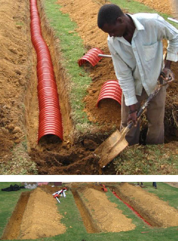
A Typical Biomat type soak away being installed. Concave chambers which are open at the bottom promote the growth of a Biological Mat of Bacteria which consume the organically rich Blackwater transferred from the Septic Tank.
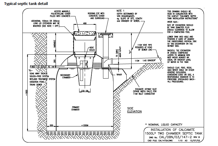
Sewer Systems
Alternatives to waterborne sewer systems
With the continuous growth of urban populations and the high incidence of people living in informal areas, there are major difficulties in providing conventional waterborne sewerage to people without sanitation facilities.
Other systems considered as alternatives, need to provide the same health benefits as waterborne sanitation while remaining affordable. They should be reliable and simple to operate and maintain.
Some alternatives are:
- Pit Latrines; The basic long drop. Informal or rural use and not supported by official policy.
- VIP; Ventilated Improved pit Latrine. Has a design and construction specification with a pedestal and means of ventilation. The VIP is the minimum acceptable and allowable level of basic sanitation.
- Septic tank with French drain: Associated with low density, low frequency application remote from waterborne sanitation facility e.g. Game reserves and farms.
- Conservancy Tanks; Sewage is pumped out of holding tanks and transported away for processing.
- Bucket system; socially unacceptable and an embarrassment to those authorities in areas where this practice continues.
- On-site sewerage treatment plants servicing selfcontained developments able to support the cost.
Ventilated improved pit (VIP) Latrine
The VIP latrine introduced in Africa in the 1970’s is widely used in developing countries especially in water short regions. It is solidly constructed and if properly used and maintained, hygienic and odourless. Pit latrines are not used in conjunction with conventional flush toilets. Only a small amount of water enters the pit and liquid is allowed to seep from the pit into the surrounding ground. In the pit, excreta decomposes into humus-like solids, water and gases. The important point is that because of the long storage time in the pit, disease causing organisms are eventually killed. Permission from the local authority must be obtained before constructing a VIP latrine.
Septic Tank and French Drain Systems
Septic tank systems treat sewage at its location, and consist of an underground tank which can either be built or purchased as a pre-manufactured unit which is then connected to a soil treatment system, commonly referred to as a ‘French drain” which is basically a subsoil percolation system.
Traditionally septic tanks were built of brick and mortar (see Fig below) and later of concrete. These were usually comprised of two rectangular chambers with a common dividing wall.
Commercially manufactured septic tanks made from suitably stable materials have been available and in use for some time. Use of these tanks has become popular as they are widely available complete with fittings, baffles and access lids. They can be quickly transported to site and are easily installed in the ground.
Whether custom built or readymade, septic tanks serve the same purpose which is to condition raw sewage which has a clogging effect on soil and reduces the capacity of the absorption field (French drain). The tank must function as both a sedimentation tank and as a digester. Wastewater enters the first chamber of the tank, allowing solids to settle and scum to float. The settled solids are “digested” by self-forming bacteria and lack of free oxygen. Baffles (“T” pieces) built into the tank minimize turbulence due to inflow and prevent floating scum from moving past the outlet of the tank. The liquid component flows through the dividing wall into the second chamber where further settlement takes place.
A relatively clear liquid between the scum and sludge layers flows out the tank for dispersion and absorption in the French drain (see diagram). The septic tank only partially treats sewage and it is the function of an absorption field to provide final treatment and disposal of the effluent in a safe and inoffensive way.
The soil on site must be suitable for the drain field to work properly; if unsuitable soil like “Ou-klip” is present it will have disastrous results in the functioning of the “French drain” or soak away, unless adequate steps are undertaken to overcome the poor drainage conditions.
There is no difference between septic tank effluent and raw sewage as far as potential danger to public health is concerned, which is a fact to be borne in mind when siting septic tank systems where communities draw drinking water from wells and boreholes. Constraints on the location of the septic tank and French drain system need to be assessed before deign or installation is commenced. See Figure 12.9 and 12.10 on the following page
Note: When digging a French drain or soak away let your trench follow the contours of the land to allow for optimum drainage and absorption.
Non- waterborne means of Sanitary Disposal are regulated by the following standard;
- SANS 10400: code of practice for the application of the national building regulations: Part P drainage and Part Q.
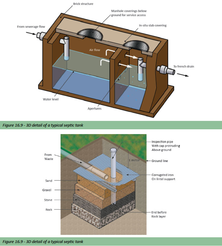
Infiltrator Chamber Systems
The Quick4 Infiltrator™ Chamber System is a direct replacement for the stone and pipe, stormwater and wastewater French drain Soakaway. Infiltrator™ Chambers promote effluent infiltration into the soil with 100% efficiency. The greater infiltrative capacity means that Chambers can require as little as half the space of old-fashioned stone and pipe systems.
Infiltrator™ Chambers offer sizing reductions of up to 50% with equal or better performance. University laboratory research and extended field evaluation has verified the infiltrative efficiency advantage of the open surface architecture provided by the Infiltrator™ Chamber Systems over old-fashioned stone and pipe systems.
An obstructing layer of biomat forms in all French drain soak ways treating septic tank effluent. As the biomat develops, the infiltrative capacity of that remaining soil area is reduced to a point where ponding occurs in the soak away. The open surface architecture of Infiltrator™ Chambers over old-fashioned stone trenches is expressed as: 100% open area / 40% open area = 2.5 more infiltration potential. With an added safety factor, a 50% smaller footprint will provide equal or better infiltration than a stone and pipe trench.
Built to last, the Infiltrator has the following capabilities:
- Chemical-resistant and UV-stable
- Powerful arch design supports axle loads of 70 kN, with 300mm of compacted cover, equivalent to as AASHTO H-10 load rating
- Chambers can be installed with 150mm of cover to support axle loads of 17kN
The superior technology of Infiltrator™ Chambers:
- Easy to handle length allows for more installation flexibility
- System sizing is determined by local shaping capability
- Advanced contouring capability with Contour Swivel Connection™
- StraightLock™ Tabs ensure straight alignment
- Compact nesting provides more trench length in a smaller storage area (50 chambers stack 1.4m high)
- Multiport™ End Caps offer a multiple piping options and minimise the use of pipe fittings
Product Line
The Quick4 High Capacity Chamber can be installed in a 0.9m wide trench. The Contour Swivel Connection™ allows the Chamber to swivel 10 degrees, left or right.
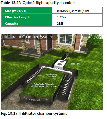
The MultiPort™ End Cap with its eight moulded-in high and low inlets allows piping to enter or exit the system from multiple directions and eliminates pipe fittings.
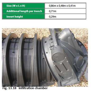
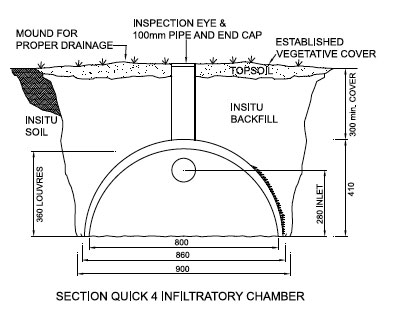
References
Alexander G D & Alexander G C. 2010. Buildaid Building and Pricing Guide 2010/11. Johannesburg: Buildaid Publishing.
Alexander G D & Van As F. 2008: Civil Technology. Johannesburg: EWA Publishing
South African Bureau of Standards. 2011/12 – SANS 10400 Part’s A and P. Pretoria. SABS Standards Division.
South African Bureau of Standards. 2012 – SANS 10252-1:2012. Pretoria. SABS Standards Division.
High Speed Gas and Paloma South Africa – www.hsgdistibutors.co.za
Mervyn Jordan.2004. SA Plumbers’ Handbook: 1st edition. Johannesburg. Pipe Trades Media Group.