Chapter 17
ELECTRICAL
Introduction
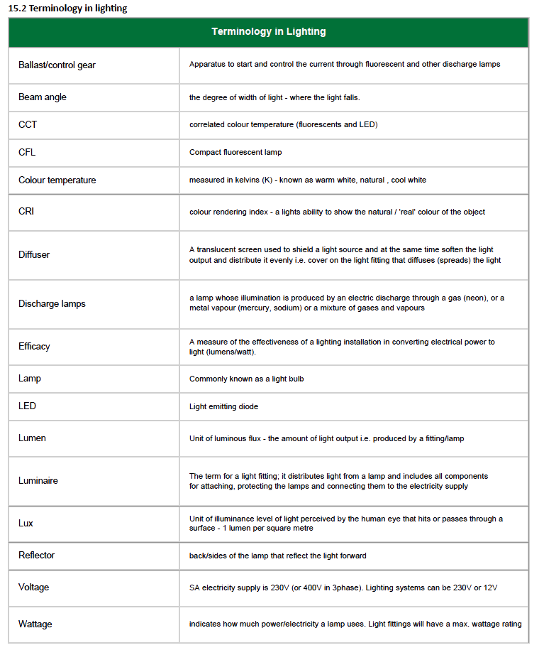
Terminology
Cables and Wiring
Standards and Regulations
Attacking the Scourge of Non-compliany, Unsafe Electrical Products and Services
Home Automation
Alternative Power (Energy) Sources
Design and Electrical Fittings
Introduction
It is very important to note that any electrical installation or work must be undertaken by a qualified and registered electrician. This section is intended to give the reader a general understanding of an electrical installation and some principles, thereby help the parties planning an electrical installation to communicate better. While the electrical trade is strictly governed by regulations the detail of what is required in an installation is sometimes sadly overlooked particularly in residential building. All too often one sees frantic chalk markings on walls showing electrical points just before plastering commences.
A simple look at electricity:
- Electricity must be allowed to flow for it to be useful.
- The flow of electricity is called Current.
- Current is measured in Amperes (amps).
- Electricity flows because of different pressures in the live and neutral wires. This pressure is called Voltage (volts).
- Flow (current) is also affected by resistance which is measured in Ohms.
- Power is measured in Watts and this is a measurement of how much electrical energy is used by something over a certain period of time.
Terminology
Conductors
Conductors allow electricity to flow freely. Most metals are conductors. Copper and aluminium are good conductors. The most commonly used conductor is copper, but brass can also be used. Aluminium is used when copper is too heavy or too expensive.
Insulators
Insulators resist the free flow of electricity. Most non-metal materials can act as insulators. The most common insulators are rubber and plastic (and some older homes still have ceramic insulation – this is very effective but no longer used). For example, the flex connecting your kettle to the plug (the wire is covered in plastic, which is an insulator) keeps you from being shocked by the electricity being conducted through it.
Volt
Unit used as measure of electrical pressure. Symbol – V. Similar to Kpa pressure in a water pipe. In South Africa the three phase voltage available for domestic use is 220 Volts (between neutral and a phase). Normally appliances sold on the market are manufactured to operate at this voltage. Sometimes appliances have settings for various different voltage operations for use in other parts of the world – make sure that the setting is suitably adjusted for this country.
Voltage drop
When all conductors of an AC installation are carrying their design load, the difference in voltage (the voltage drop) between the point of supply and any point of outlet or terminals of fixed appliances should not exceed 5 % of the standard or declared voltage.
Ampere
Unit used as measure of electrical rate of flow or the measure of the amount of electric charge passing a point in an electric circuit per unit. Symbol – A. Similar to litres per minute in a water flow system. Each and every appliance connected to an electricity supply system will draw a certain amount of current in Amps when in operation. A toaster makes use of this current flow through a filament to generate heat in order to brown the toast. The light bulb is similar except that the heat generated is so high that light energy is given off.
Watt
Unit which shows the current drain of consumption of an appliance connected to a circuit. Symbol – W. Most appliances are rated in Watts. It is a very useful unit to determine the size and rating of a conductor for a particular appliance. A variation of the Watt is the Watt-hour and this unit shows the electrical consumption over a fixed period. The electrical supply utility (In South Africa, Eskom or City Power) makes use of this unit to charge for the use of electrical energy.
Domestic Voltage
Domestic Voltage means voltage not exceeding 230V +/- 10% alternating current phase to neutral.
Low Voltage
Should not be confused with the low voltage application usually used for lighting and other appliances that commonly run at 12 volts. Low voltage technically means a set of nominal voltage levels that are used for the distribution of electricity, the upper limit of which is generally accepted to be an A.C. voltage of 1 000 V (or a D.C. voltage of 1 500 V).
Medium Voltage
Means a set of nominal voltage levels in the range 1 kV to 44 kV that is above low voltage and below high voltage.
Circuit/Conductor
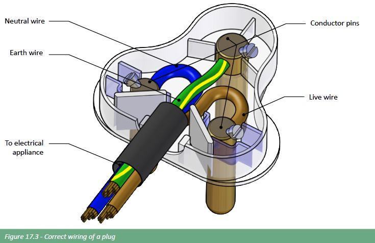
A circuit is a conductor (e.g. copper wire) connected in such a way that electrical energy is allowed to flow through it. In household wiring there are normally two conductors that make up a circuit; one is the live conductor and the other the neutral. Very often they will be colour coded to make identification of the type of circuit and conductor easy. A third conductor (normally a non-insulated copper wire) is provided for an earth return, this is a safety feature should the insulation or proper connection of live conductors fail.
Circuits
Electricity enters a home via a 220v cable into the distribution board which contains circuit breakers (or fuses in older houses). These circuit breakers divert the electricity along wires running in conduits in the walls and roof, forming separate circuits around a house which deliver electricity to all the switches and power points.
A house has multiple circuits to help the electrical current stay small, reducing the risk of overloading the circuits. Some appliances, such as a stove, dishwasher, air-conditioner/ heater or dryer, draw more power than say a light point and may require their own circuit.
It is most important that the correct size of wire or cable is used for the maximum potential load on a circuit. The following specifications may be used for guidance:
- 1 or 1.5 mm² for lighting, depending how many fittings are connected;
- 2.5 mm² for power circuits and ring mains again depending on how many socket outlets are connected to the circuit and their application;
- 4 or 6 or 10 mm² for cookers, water heaters and air-conditioning, depending on current demand and output temperatures.
Note:To work out how many watts an appliance is drawing, check the voltage and the amps of the appliance.
Volts x Amps = Watts
Therefore:
- 1 Amp at 12 volts = 12 watts
- 1 Amp at 120 volts = 120 watts.
Watts/Volts = Amps
Therefore:
A 1200 watt hairdryer at 120 volts draws 10 amps (1200/120 = 10).
Each circuit must be protected by a device (circuit breaker) rated according to the maximum load on the circuit. Each power and lighting circuit is usually limited by the number of outlets or appliances served by that circuit. Lighting circuits will probably be restricted to 10 or 15 amps, and power circuits serving single 16 amp sockets, to 20 amps; for directly wired fixed items such as domestic hot water heaters and air-conditioning, to 30 amps; and circuits to cookers, some of which can be rated at 10 kW, to 60 amps or more.
The number of circuits in a house will vary from house to house A typical house measuring 180 m2 may have seven circuits – two for the lights, two for plug points (sockets), one for an air-conditioner/heater, one for the oven and one for the hot-water system. To check how many circuits one has in a home simply count the number of circuit breakers in the distribution board.
Fuse
A safety device that breaks the flow of electricity whenever a circuit is overloaded. Modern installations do not use fuses as safety devices. Older homes and building may still use fuses. Each circuit will have a current rating. Should that current rating be exceeded, it may become dangerous and may cause a fire, injury or even death. To prevent this, a fuse is placed in line with this circuit, always on the source side, and breaks the flow of electricity by overheating and melting. A fuse is chosen with a rating always slightly less than the maximum current rating of a circuit. Fuse wire is still readily available and is rated in amps. More commonly, fuses will be found in some electrical and many electronic appliances to protect them from possible internal faults that may occur and cause large current flows that result in serious damage.
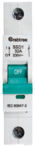
Circuit breaker
Performs the same function as a fuse, but needs only to be reset, not replaced. These have now replaced the traditional fuses, and are chosen and connected into a circuit in exactly the same way. When the current flow in a circuit exceeds the rating of the breaker it will simply trip, cutting off the electricity supply to that circuit, protecting it from damage. Once the fault has been cleared, the circuit breaker is reset, thus restoring the supply. They are located in the distribution box of the house and also in the utility supply meter box. Every breaker should be clearly marked in order for faulty circuits to be easily identified and isolated (e.g. lights, plugs, geyser, stove). A circuit breaker is also a switch.
Note: A geyser consumes the most electricity in a home making up approximately 60% of an electrical bill. Installing a timer can save 40% – 60% of the geyser cost.
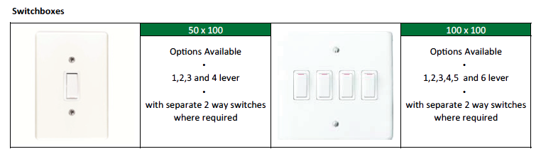
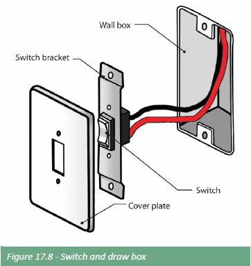
Switch and isolators
This is a device for breaking the flow of current. Switches come in various shapes and sizes but all operate on the same principle. An important factor when choosing a switch is its rating. A reputable manufacturer will always indicate the operating voltage and current rating. For instance, a light switch must not be used as a stove isolation switch, simply because the rating of the light switch will be too low for the stove current drain, causing it to overheat and fail.
Switches is a residential building would include switches in the distribution board and the common switches indicated in the following figure.
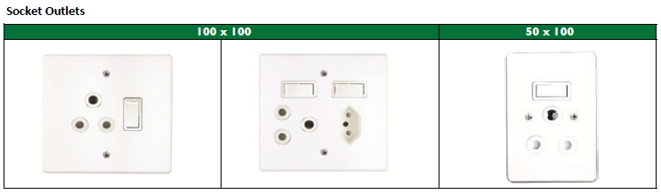
Sock outlets (plugs
One must consider the number of electrical appliances in the modern home when deciding on the number of socket-outlets per room and whether they should be single or double socket outlets or combinations of Euro style outlets in order to minimize the need for adaptors and extension cords. Socket outlets should be carefully positioned in places where they are most needed; where there are only two sockets in a room they should preferably be placed on opposite walls. Different fixing heights may be preferred in some situations, but, although not yet standard practice in the industry, it is suggested that no socket outlet should be lower than 300 mm above finished floor level. The preferred height for socket outlets over worktops is approximately 1100mm above floor level, but is also dependent on the kitchen design and layout.
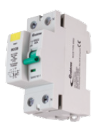
Earth leakage unit
This device is able to detect small imbalances between the earth conductors and the supply, indicating leakage of electricity down to earth. When this happens the earth leakage switch automatically turns off or ‘trips’. A small test button is provided and should be used to test the unit periodically. It is a vital safety feature for any installation and should be installed.
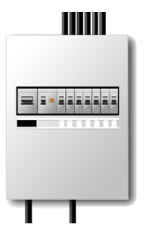
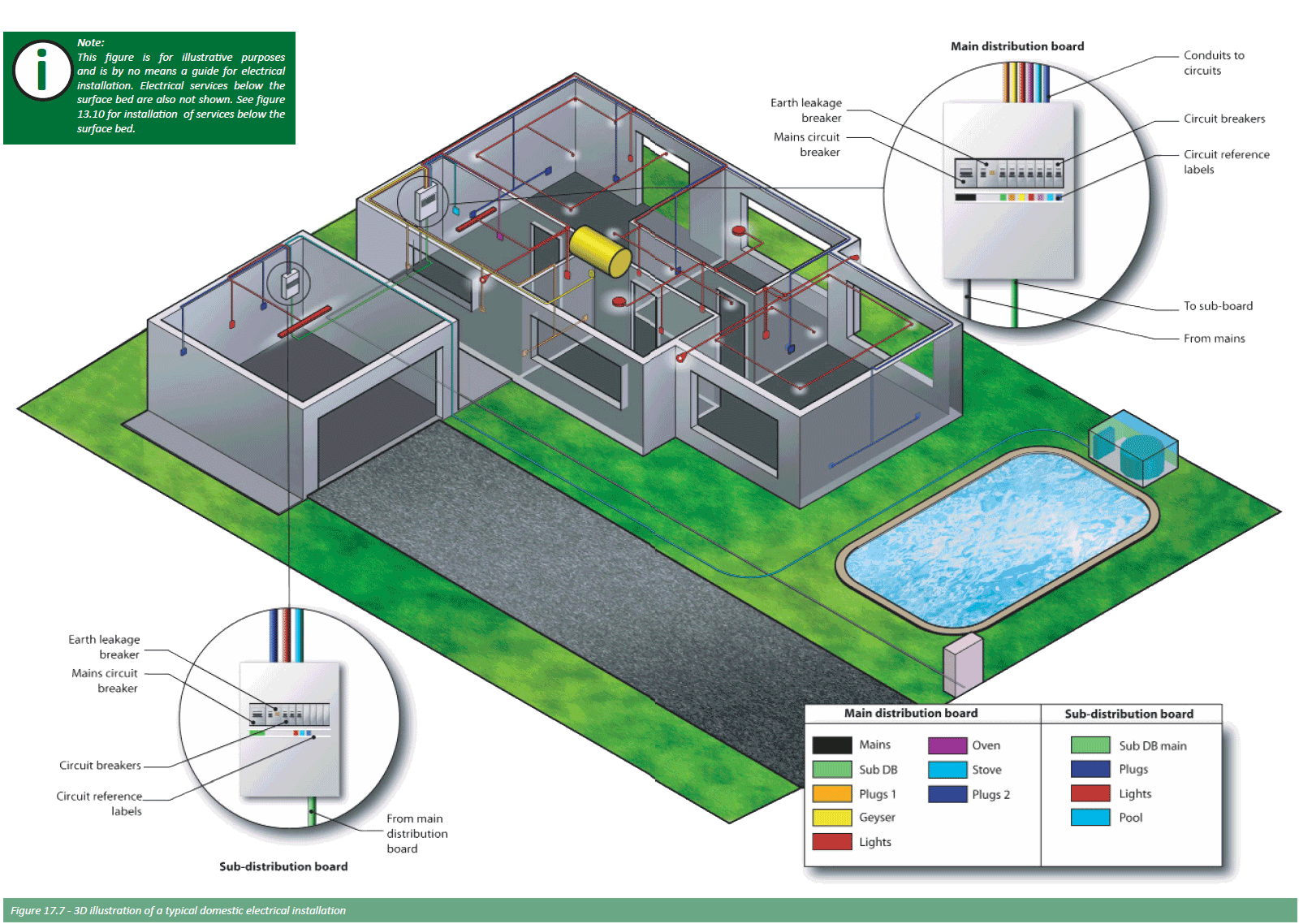
Distribution board
A distribution board (DB) is where the electrical supply is distributed from within the building. The main supply cable comes into the board and is then distributed to the breakers and from there to all the circuits, e.g. lights, plugs. It usually houses all the contact breakers, earth leakage unit and may house items such as a door bell transformer and timers. Various sizes of distribution boards are available. The main distribution board is usually in the house where the main cable electrical enters and smaller boards, together with contact breakers and possibly earth leakage units are at other points, such as swimming pool pumps, gate motors and outbuildings.
Various types of distribution boards are available; as surface mounted, flush mounted or floor standing; with closing doors or see through plastic covers or doors and in different sizes which are determined by the number of circuits required within the board to which some manufacturers refer to as modules and others as “way” e.g. 8, 12, 18, 24, 36, etc. way or module.
The interior of the distribution board is pre-fitted with a clip tray or DIN rail for mounting the miniature circuit breakers (MCB) and other devices. These two different types of MCB’s are referred to as “mini rail” or “DIN” which are only interchangeable if special adaptor brackets are used.
Whilst mini rail MCB’s can be slightly narrower than DIN MCB’s thus giving an advantage of fitting more into the same space available the number of accessories on the market for this type of distribution board is limited as many manufacturers are now using the DIN format for their equipment.
With the DIN format the normal range of earth leakage units, disconnecting switches as well as MCB’s are available. In addition to this various types of meters, time switches, pilot lights, surge arresters, etc. are manufactured as well as GSM (Global System for Mobile Communications) units to facilitate remote monitoring and control of events via a cell phone. This now makes the DIN type of distribution board very versatile. Distribution boards can be purchased either as an empty enclosure to enable the contractor to equip it or as a ready wired standard unit or as a specially manufactured item to the clients requirements. Also available are distribution boards for specific applications such as swimming pools, ready boards for low cost housing, irrigation systems, etc.
Each distribution board must be controlled by a switch-disconnector (mains or main switch) The switch-disconnector should:
- be mounted in or next to the distribution board
- in the case of the main or first distribution board of an installation, be labeled as “main switch”
- in the case of a sub-distribution board, be labeled as “sub-main switch” or “main switch” if the board is labeled “sub-board …”;
- in the case where an alternative supply is installed (emergency supply, uninterruptible power systems (UPS), etc.), be labeled as required, and
- have a danger notice on or near it. The danger notice should give instructions that the switch-disconnector be switched off in the event of inadvertent contact or leakage.
A distribution board must comply with the requirements of SANS 10142 and each item of electrical equipment used in a distribution board should comply with the requirements of this standard:
- The distribution board must be suitable for the environmental conditions in which it operates;
- Distribution boards shall be protected against corrosion;
- Any point of a distribution board that has to be reached during normal operation must not exceed a height of 2.200 mm above floor (or walking) level. However, the board may be mounted higher if it can be disconnected from the supply by a switch-disconnector that is less than 2.200 mm above floor level. Unless a residential distribution board is housed in an enclosure and direct access cannot be obtained by an infant, no part of an indoor distribution board can be less than 1.200 mm above the floor level and no part of an outdoor distribution board can be less than 0.200 mm above the ground level;
- A distribution board must not be mounted in a bathroom, or above a fixed cooking appliance or in a position where a stationary cooking appliance could be put below it, unless the enclosure provides a degree of protection, or within a radius of 1 m from a water tap or valve (in the same room), unless the enclosure provides a degree of protection;
- if an installation is likely to be extended, a distribution board with spare ways should be fitted;
- Each unoccupied opening of a distribution board must be fitted with a blanking plate;
- Unless obvious, permanent labeling must identify all incoming and outgoing circuits of the distribution board.
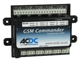
GSM (Global System for Mobile Communications)
GSM is a telemetry system using cell phone technology. A sim card from one of the cell phone service providers is required to be installed in the GSM unit to enable communications between the unit and one or more cell phones and other GSM units if required. Most GSM units are suitable for mounting directly into a DIN distribution board. GSM units normally have easy step by step programming procedures to allow the end user to monitor and control various events.
This programming can be done via a computer using the software supplied with the unit or via sms using a security code. From a cell phone it is possible to switch lights and other electrical circuits on and off, control electric gates, arm and disarm intruder alarm systems, control irrigation systems, etc. Intruder alarm systems can also be monitored via the GSM unit sending an sms message to a cell phone or number of cell phones of the end users choice giving details of which circuit has been triggered in plain text i.e. “lounge PIR activated”, “front door opened”, etc. It is also possible to send an sms message when there is a power cut or loss of power at the premises. This is very useful as it allows the end user if away from the premises for a prolonged period to make arrangements for the power to be restored before foodstuff stored in freezers and refrigerators have time to deteriorate.
The unit can also be programmed to send selective messages to individual cell phones. Many GSM units have an on board processor to enable functions to be performed on a regular basis by day and time, much like a time switch. This processor can also be programmed for logic functions e.g. If [ABC Happens] then [do something (turn on D for example)]. The advantage of this type of system is that the end user can monitor their premises no matter where they are providing they have cell phone coverage.
Electric Motors
There are various applications for electric motors such as boreholes, irrigation and swimming pool pumps, security gates and garage doors.
Borehole and irrigation motors are supplied as three phase (380- 400V) or single phase units (220-230V) and require special starting and control equipment, it is not advisable to supply them via only a circuit breaker directly from the power supply as this does not provide adequate protection for the electric motor. Borehole pump motors burn out very quickly if they are not cooled down by the water being pumped from the borehole. Special protection in the form of a “phase angle relay” have to be installed to suit the particular motor and pumping characteristics to guard against this “dry running” condition. It is always better to have a borehole pump pumping to a static location such as a storage tank (fixed back pressure and head of water) than directly to an irrigation system where the back pressure and head can change due to different sprinklers and taps being opened as the phase angle relay could see this as a fault and nuisance tripping of the pump would occur. Various types of Borehole Starter panels are available for different applications and it is best to contact a supplier of these panels when planning to install a system.
Irrigation or booster pumps also require special control panels to protect the electric motor and also if necessary damage done by pipe bursts or blockages. They can be manufactured with various types of control systems such as float switch, liquid level, irrigation controller, time switch, pressure switch, flow switch, etc. Again check with a control panel supplier when planning your system and seek their help for the best possible options.
Swimming pool pump motors are normally single phase and controlled from a purpose made “Pool Box” which is available off the shelf in various formats, i.e. weatherproof, with circuits for low voltage pool lights, 15A domestic socket outlets, etc.
Spa baths also require a special control box to not only control the pump motor but also the heating elements. These units again are available as off the shelf items in various formats. Control panels for gate motors and garage doors are also available as off the shelf units in various formats depending on the type of gates and doors installed. Whilst 220/230V AC motors are available for these applications it is always advisable to use low voltage DC motors so that the on board battery in the control panel will still operate the gates and doors during a power failure.
Daylight sensors
Automatic daylight sensors (photocell controls)
These can be used effectively for controlling external lighting and saving on electricity costs.
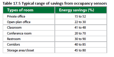
Energy efficient occupancy sensors
Energy efficiency sensor switches and sensors are available, based on passive infrared and ultrasonic technology. They are designed to switch lighting off when a room is not unoccupied and back on when occupied.
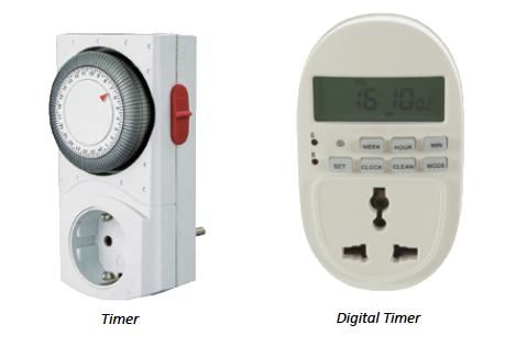
Timer
A device may be used to switch the electrical supply on and off at predetermined times over a 24 hour period. A commonly used timer is for the pool pump set at certain intervals to switch the pump on and off. With the need to conserve energy, a timer installed for geysers is now common place. Heating water in a geyser only at certain times during the day saves a lot of energy.
Inverter
A power inverter is an electrical power converter that changes direct current (DC) to alternating current (AC) The converted AC current can be produced at any required voltage and frequency with the use of appropriate transformers, switching, and control circuits. A common use of an inverter is in a solar energy installation. Solid-state inverters have no moving parts and are used in a wide range of applications, from small switching power supplies in computers, to large electric utility high-voltage direct current applications that transport bulk power.
Transformer
If a voltage other than the mains voltage (220 Volts) is needed to supply electricity to an appliance or building, a transformer is necessary to step this voltage up or down. Low voltage lighting, as its name suggests, needs 12 Volts in order to operate safely and correctly; a transformer may be used to step the mains down to this level. On the other hand, industry may need higher voltages than can be supplied by the utility and uses transformers to step up to the required level.
AC/DC
AC is the abbreviation for alternating current and DC for direct current. AC is the type of electricity supplied by the electricity supply utility to our industry and homes. DC is the type of electricity that would be supplied by a battery or an appliance such as a car battery charger where the voltage and current are constant. All the appliances found in our homes that operate on the mains supply are designed to work with AC. Some appliances however need batteries, such as portable radios and these work on DC.
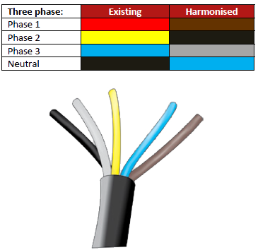
Single/Three phase
Single-phase is an electrical supply with only one live phase, plus the neutral. Three-phase is the most commonly supplied electricity, 230/400 volts, from which 230 volts can be obtained between a phase and neutral in a four-wire system, but can be higher when used in commercial and industrial applications. Looking at the cable three phase would have four wires excluding earth and the single phase would have two wires excluding earth. Some industrial motors and machinery require three phases to operate.
Meter
The electricity meter is a very sensitive device that measures consumption in units of 1000 watts per hour and is expressed in kilowatt-hours. In modern installations, it will be located in a weather-proof housing just outside the boundary and will more than likely have a peep hole so that the meter reader can take readings without having to opening it. Older installations have been mounted on the same board that houses the contact breakers and/or fuses inside the building. This device makes it possible for the electricity supply utility to charge for the amount of electricity used over a period of time. The more electricity used, the more units indicated by the meter. The rate per unit will be multiplied by the total number of units for the period measured, giving a total value for the amount consumed.
Relay unit
In an effort to save energy, it has become common practice for many municipal supply utilities to install in residences a relay unit that is remotely controlled to switch off the geyser during a period when there is little or no demand. This has little effect on the individual household since the off time is relatively short but cumulatively, a sizable saving is achieved.
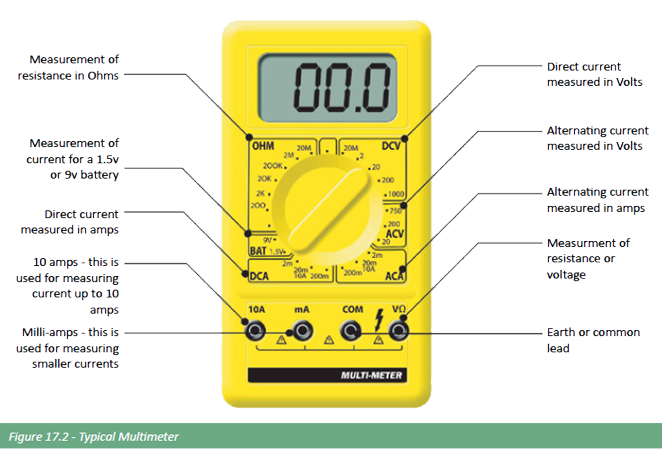
Multimeter
A multimeter is an electronic measuring instrument that offers a number measurement functions in one unit. A multimeter would usually include basic features such as the ability to measure voltage, current, and resistance A multimeter is a hand-held device useful for basic fault finding and can measure to a very high degree of accuracy. It can be used to troubleshoot electrical problems in a wide array of electrical devices such as electronic equipment, motors, domestic appliances, power supplies, and wiring installations.
Busbars
Bare copper or aluminium conductors fixed inside a distribution board, to distribute electrical power to the circuit breakers.
Surge protection
Before the introduction of hi-tech electronic equipment such as computers, hi-fi systems, micro-wave ovens, televisions, etc. electrical surges were not considered a major problem. These hi-tech items require a stable power supply as they are very sensitive to fluctuations in electrical voltage and current. A power surge, or transient voltage is a spike or increase in the normal voltage that the equipment is designed to operate at.
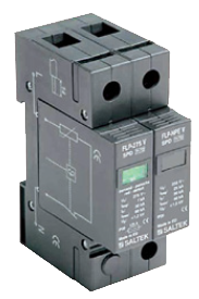
A simple explanation for this phenomena is that if in a normal household the water pressure in the pipes were to increase significantly the geyser would probably burst, when electrical equipment sees a power surge the electronic components “burst”. The surge protectors act as pressure relief valves in the electrical system. Because of the vulnerability of this hitech equipment some insurance companies are refusing to give insurance cover to equipment that has been damaged by lightning and/or voltage surges so it now becomes imperative to install surge protection devices (SPDs).
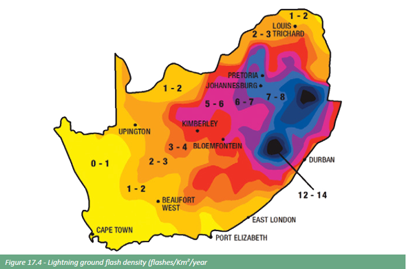
The most dangerous surges are those caused by direct lightning strikes to a building and can be calculated using the method specified by SABS. This risk increases if the building is located in an exposed position, such as on the side of a hill. Surges due to network switching and adjacent lightning strikes are usually the least dangerous but occur most frequently. This is expressed as the “lightning ground flash density” and is detailed on the map below. There are three main categories of SPDs, current-diverting (Class I) and voltage clamping (Class II and III).
Class I SPDs (10/350) lightning current arresters are able to divert large surge currents such as direct lightning strikes but must be used in conjunction with Class II SPDs. Whenever a building has external lightning protection such as a mast or conductors on the building Class I SPDs must be installed. Class II SPDs (8/20) surge arresters are able to survive lower amplitude surges in areas where direct lightning strikes are not expected and must be installed in main distribution boards as a minimum requirement according to the regulations in SANS 10142-1. Although this regulation requires that the SPDs must withstand a nominal surge current of 5kA and a peak surge current of 10kA it is recommended that higher rated SPDs be installed, say nominal surge current of 10kA and 25kA peak surge current.
Class III SPDs (8/20) surge arresters are installed to dissipate any surges that are induced between the electrical distribution board and the equipment to be protected. These Class III SPDs must always be used in conjunction with Class II SPDs. If the Class III SPD does not have an internal disconnecting mechanism the circuit that it is used on must also be supervised by an earth leakage device.
The figures in brackets (8/20) next to the SPD Class represents the response time in micro seconds (μs). The first figure is the time that the SPD takes to ramp up to the maximum nominal discharge current, in this case if the SPD had a nominal discharge current of 10kA it would take 8μs to ramp up 10kA and then 20μs to decay to 50% of 10kA (5kA). From this it can be seen that when a Class I SPD with a ramp up and down figure of 10/350 is used although being able to handle a higher current it is much slower in doing so, which is why a Class II SPD needs to be used in conjunction with it to make the residual voltage low enough to safe guard the installed electrical devices.
There are SPDs on the market that combine Class I and II characteristics. Class III SPDs would normally be installed in individual circuits as close as possible to the item of equipment that is being protected and are available as individual plug-in units and extenders (surge protector power strip). Many SPDs have flag or LED indications to show that the unit is healthy or “blown” and these types should be used wherever possible. It is also worth noting that surges can also be experienced on incoming telephone lines, data lines and antennas and that special SPDs are available for these applications.
Cables and Wiring
Open wiring
Open wiring consists of single-core insulated conductors that operate at not more than 250 V to earth; however, this is not a recommended installation method for new installations. Open wiring can still be seen in older buildings and homes.
Co-axial cable
Screened single-core co-axial communication cable sometimes referred to as aerial wire, has a single copper strand insulated by thick plastic and surrounded by foil and screen wire. It is commonly used to connect an aerial to the TV.

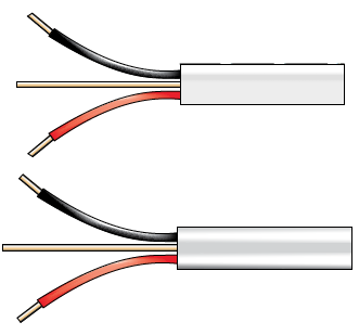
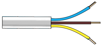
Surfix or Norsk cable
Popular cables used for domestic wiring applications; available in either flat or round and commonly referred to as “twin and earth”. They have two single copper strands insulated with PVC and a bare single copper earth wire. Norsk cable has the earth wire between the two strands. Round surfix cable has an extra strand of PVC material embedded to maintain its “roundness”. Surfix cable also has an outer foil shield to prevent induction. It is sold in a variety of sizes. Norsk cable is available in black or white whereas round Surfix is always white.
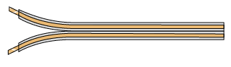
Flex or ripcord
A twin stranded wire normally used for bells, lamps and the wiring of alarm systems. It does not have an earth wire. For some ripcords the outside of one strand is marked with either a ridge or a different colour to identify which is to be used for the positive (live) and which for the negative (neutral) side, however most ripcords have a red and white satin insert in one strand for this purpose.
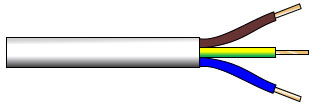
Cabtyre – Three core
The most popular cable of all. It is extensively used for extension leads and supply cables to appliances. It is sold in a variety of sizes and colours.
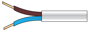
Cabtyre – Twin core
Mostly used for lamps and other appliances that do not have to be earthed, it is sold in different sizes and colours.
3-core
The most popular cable of all. It is extensively used for extensions and supply cables to appliances. It is sold in a variety of sizes and colours.
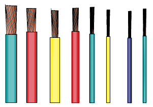
House wire
Used for the internal wiring of buildings. It is sold in a variety of thicknesses and colours and typically a seven strand core. The earth wire is always bare.
Armoured cable
Armoured cable is normally used to transfer power either underground or overhead. The construction is normally the inner cores (which are generally multi strand) being individually sheathed, then covered by an initial overall plastic sheath, followed by the protective wire armour with a final outer sheath to hold it all together. The inner cores may number two, three or four depending upon the application. The wire protective armour should always be earthed at the supply end to ensure that it cannot become live if the cable is severed or a fault should develop within the cable.

Standards and Regulations
The Occupational Health and Safety Act, 1993
The Act (Act No. 85 of 1993) (OHS Act), which is administered by the Chief Inspector of Occupational Health and Safety of the Department of Labour, requires that all electrical installations comply with the requirements of SANS 10142-1. It also requires that an accredited person, as defined (master installation electrician, installation electrician or electrical tester for single phase), will issue a Certificate of Compliance (CoC) for an electrical installation and that the certificate should be in the form of the Certificate of Compliance published in SANS 10142 (see a specimen of this certificate in this section).
Inspection
Normally, inspection precedes testing and should be done with the installation isolated. Inspect the installation to confirm that equipment has been selected and installed in accordance with SANS 10142 (SABS 0142) and that equipment it is not so damaged as to impair safety.
Compulsory standards
- Compulsory specification for circuit-breakers, as published by Government Notice No. 1090 (Government Gazette 20461) of 17 September 1999. (VC 8036);
- Compulsory specification for earth leakage protection units, as published by Government Notice No. 2286 (Government Gazette 10987) of 16 October 1987. (VC 8035);
- Compulsory specification for manually operated switches for fixed installations, as published by Government Notice No. R438 (Government Gazette 18779) of 3 April 1998. (VC 8003);
- Compulsory specification for plugs, socket-outlets and socket outlet adaptors, as published by Government Notice No. R442 (Government Gazette 18779) of 3 April 1998. (VC 8008);
- Compulsory specification for the safety of electric cables with extruded solid dielectric insulation for fixed installations (300/500 V to 1 900/3 300 V), as published by Government Notice No. R1169 (Government Gazette 21759) of 24 November 2000. (VC 8075);
- Compulsory specification for the safety of flexible cords for electrical appliances, as published by Government Notice No. 1212 (Government Gazette 16598) of 11 August 1995. (VC 8006)
SANS 10142 (SABS 0142) is concerned with ensuring the basic safety of electrical installations and to ensure the protection of people, animals and property and the proper functioning of an installation.
The designer of an electrical installation should be aware of:
- the characteristics of the power supply,
- the nature of the demand, and
- the operating environment of each part of the installation.
It is especially important to be aware of the activities of occupants of a building. For example, the occupants might be engaged in wet processes or in the handling of flammable or explosive materials. These activities will influence the design of the installation. If a client wants more safety features for the installation than those prescribed in SANS 10142 (SABS 0142), such features have to be included in the contract documentation.
The provisions of SANS 10142 (SABS 0142) apply only to the selection and application of electrical equipment, appliances and accessories, which are part of the fixed electrical installation. They do not apply to the construction and safety of the equipment, appliances and accessories; those aspects are dealt with in other standards.
The Electrical Contractors’ Association of South Africa – ECA (SA)
The Electrical Contractors’ Association of South Africa – ECA (SA) – is a employer organisation registered in terms of the Labour Relations Act. Established in 1950, the ECA (SA) represents members and their interests in the labour Relations arena and in the technical and regulatory mechanisms governing the Electrical Industry.
On the ECA (SA) web site members of the public can search for and find Electrical Contractors registered with and approved by the ECA (SA), get answers to questions, contact the ECA (SA), browse classified and job adverts placed by ECA (SA) members and read the latest news from the association.
Visit www.ecasa.co.za
Visit the ECASA website
The scourge of non-compliant, unsafe electrical products and services
With the influx of imports from around the world, specifically within the construction industry, it has become difficult to differentiate between good quality, compliant, products and those that are not. This and the resultant safety and functionality risks apply to suppliers of products, construction-industry professionals and contractors, end users in commercial and industrial buildings and homeowners.
While all elements in the construction industry contribute to the health and safety features of a building project, electrical components and installations are particularly dangerous if they do not comply with basic safety standards. As far as the homeowner is concerned, with the Consumer Protection Act now firmly in place, everyone in the supply chain must be vigilant to ensure quality and compliance of products and services. Entities that recommend, specify, distribute or install non-compliant products or that provide sub-standard services could be held liable for resulting damages.
While there are legislated regulations and compliance processes in place for products and services (By virtue of SABS standards, the NCRS regulatory body and the Department of Labour as custodian of the Occupational Health & Safety Act), there is widespread and continuous evidence on a large scale that their measures aren’t enough to ensure the desired degree of compliance. Amongst the root causes of this problem is the lure of low prices and suppliers’ deliberate, dangerous compromising of quality at the expense of users’ safety. There is also misinformation and lack of knowledge on the part of specifiers, suppliers, installers and users. This situation has prompted a group of organisations within the electrical industry to form the SAFEhouse Association to help ensure that products and services comply with safety regulations.
Safehouse aims to back-up and to co-operate with standard-setting and regulatory entities to counteract the proliferation of unsafe products and services that are freely offered and purchased on the open market.
Safehouse aims to inform – to educate – users and all entities in the supply-chain so as to encourage them to be discerning in their selection of electrical products and services. SAFEhouse members fund these communications and also undertake to supply only products and services that are up to standard. Where no local standard exists, members undertake to ensure their offerings comply with credible international standards or other benchmarks.
Everyone within and affected by the industry has a responsibility to support initiatives aimed at stamping out the use of unsafe products and services. It is no exaggeration to state that the credibility and reputation of the electrical industry is at stake. As the supplier, it is vital that the industry takes a constructive and action-oriented stand, for its own good and that of its customers.
The scourge of sub-standard products has extended to the provision of services as well: Electrical installations are now being offered at low prices by unqualified or poorly-qualified contractors who also use sub-standard products and compromise quality in a number of ways in order to gain business.

Home Automation
Home automation systems vary in complexity from the simple; which allows pre-programmed light dimming combinations to be selected instantly by selecting a desired pre-setting. (Instead of dimming lights individually to create an ambiance, one button alters the lighting and transforms the mood of your home.) to the very complex; which can almost integrate all the items listed below into one control system. In ‘smart homes’ any number of sensors and controllers can be connected together to interact, thus making the home seem ‘intelligent’.
Security
- Interface directly with security cameras
- Remotely view videos and alarms at your own convenience
- Automatic lighting control – responding to alarm conditions
- Shutters and blinds control
- Double communication, ensuring alarm condition reports are transmitted to Security Company/armed response and owner via telephone, GSM and fixed line.
- View status of security at all times on a digital representation of the premises, with simple arming of your alarm system via remote control.
- Intelligent interpretation of security signals
- Can be integrated with other automated systems.
Lighting and power outlets (plugs)
- Control and monitor mains voltage
- Automate lights for mood control (dimming and switching) or deactivate during the day or if no movement is detected for long periods of time.
- Can remotely turn on specific fixed appliances e.g. geyser
- Monitor plug points drawing excessive amps for long periods of time.
Audio
- Interface directly with television and radio stations, DVD’s etc.
Climate Control
- Monitor and control underfloor heating.
Monitor and regulate air conditioning to keep a constant, comfortable temperature throughout the house,
Outdoors
- Irrigation – set individual timing as required by each irrigation station or valve.
- Schedule an irrigation sequence that will execute depending on integrated weather information considering rainfall, outdoor temperatures and soil moisture content.
- Control swimming pool functions such as automated pool covers, chlorine testing and dispensing, filtering, lighting, temperature etc.
- Control outdoor lighting.
Bathroom
- Heat up towel rails
- Air extraction
- Jacuzzi control
Alternative Power (energy) sources
During power outages consumers are increasingly turning to alternative types of electrical power and/or using alternative electrical power to augment that which is supplied by the utility provider. Alternative power falls into two categories namely non-renewable energy such as petrol and diesel generators and renewable energy such as solar, wind power, hydropower, etc. A generator that runs on biofuel would fall into the renewable energy category.
Equally an uninterrupted power supply (UPS) can be either of the above categories depending on the source of the energy for the unit. A UPS that takes its supply voltage from the grid (the utility provider) would fall in the non-renewable energy category whilst a UPS taking it supply voltage from solar panels as an example would be using renewable energy.
Generators
Small generators are usually expensive to run due to their inefficiency compared to the large turbine type generators used by the utility providers. For this reason the majority of consumers only use generators as standby or emergency power for security lighting, fridges and deep freezes.
Manual and automatic changeover systems as well as automatic starting equipment are available to make it convenient for the consumer to change from one power source to the other. When using the alternative power source the reticulation system of the premises should be so installed that only essential equipment is powered.
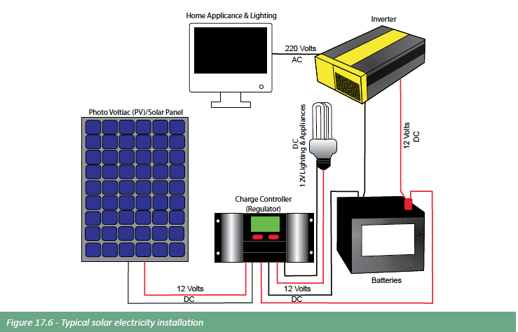
Solar Energy
As the name suggests solar energy is derived from the suns solar radiation via photovoltaic cells. A number of these cells are connected in series and/or parallel to produce a suitable voltage and current that can then be converted, solar cells produce DC voltage as against AC voltage used by most consumers, to the standard AC supply voltage. The energy collected from the solar cells can either be converted via an inverter and used directly (on grid system) to supply equipment or stored in batteries to be used at a later time (off grid system). A combination of the two systems can also be used but the number of solar cells must obviously be increased to cater for both power requirements.
These systems can be purchased in various sizes (output Watts) under the general heading of “Hybrid Solar Power Systems” although many manufacturers have their own trade names such as “Hyrec”, etc. It is important to ensure that the inverter which converts the DC voltage to AC voltage is a pure sine wave unit and not a modified sine wave (also referred to as a square wave) unit. Although a modified sine wave unit is less expensive certain electronic equipment, fridge and air conditioning motors, etc. will not operate correctly on this type of unit. The manufacturing costs of these units have decreased dramatically during recent years and the efficiency has increased but the initial outlay to power the complete premises by solar power is still relatively high.
Wind Power
Wind generators can be used as alternative power and would operate with equipment similar to that used by solar energy except that the solar panels would be replaced by the generator. The wind generator itself normally consists of three blades, basically a propeller that drives an alternator either directly or via a gearbox. This unit is then mounted on a pole or tower structure depending on its size and connected to a charge controller to stabilise the voltage and current. Whilst solar power can only be generated during daylight hours wind power can be generated at any time night or day providing that there is sufficient wind available. This makes wind power somewhat unpredictable for on grid systems but can be a very cost effective way of producing energy when used as an off grid system. Small off the shelf wind power systems, 400W to 1000W, are available and can be installed relatively easily by the consumer.
Heat pumps
A heat pump heats water by using heating technology similar to that used in air conditioners and refrigerators. The heat pump unit It is placed outside the home and is easily connected to a new or existing geyser, using the geyser as a hot water reservoir. A heat pump offers the home owner a way to use electricity to heat water efficiently. Where a geyser uses three units of electrical energy to produce three units of heat energy, a heat pump converts just one unit of electrical energy into three units of heat energy.
See Plumbing section for more information on heat pumps and solar water heating
Design and electrical drawings
Without proper drawings and specifications it becomes extremely difficult to undertake an electrical installation, if not impossible. In commercial and industrial projects where the electrical installation can be complex, drawings are in most cases provided by the architect. Unfortunately in residential building electrical drawings are generally sadly lacking. Home owners are urged to firstly employ an architectural professional to provide a full service and then make absolutely sure that an electrical drawings is compiled.
An electrical drawing doesn’t show the wiring, cable or conduit layout, its shows: where each electrical point is situated within the building and a brief description and a specification if necessary. An example of a simple electrical legend is shown in Figure 13.7 on the following page.
When compiling the electrical drawings the architect and home owner will look into the functionality of the home and the home owners lifestyle and needs. Below are some design tips:
Other points that may not technically be electrical or are installed by another contractor can also be included on the electrical layout drawing some examples are:
- Telephone
- Computer connectivity
- Security systems
- TV connectivity including satellite or aerial point
- Home automation
- Sound systems
- Intercom
- Electric gates
- Water storage tanks
- Swimming pool
- External lighting
- Air-conditioning
- Photo Voltaic (solar) panel points and related connections
- Heat pumps
- Heating points
- Automated Irrigation
- Boreholes
Notwithstanding what has been mentioned already here are
some design tips:
- The height at which plugs (sockets) and switches are set may vary but the norm is 1040mm above floor level for a light switch, 300mm for a plug (socket) and 1100mm for a plug (socket) above a working counter.
- When placing plugs and lights, picture living and working in the proposed spaces of the building
- Go through the drawings room by room and take furniture into account. This applies to lighting and plugs.
- If home automation systems are going to be installed it is wise to design the installation with a consultant.
- In the kitchen area, work closely with the kitchen manufacturer/installer. Plug points are inexpensive as a percentage of the building cost. Rather have two or three too many than be short; extension cables across a kitchen counter never look good. Properly position lights and correct light fittings are critical in a kitchen and again the kitchen units and accessories must be taken into account. The position of the stove is important because of the stove isolator, moving the stove isolator point after building can be costly. Other fittings like extractor fans must be considered.
- The electrical points in a bedroom need to be considered with the furnishing in mind. Television, Data, ceiling fans, air-conditioning and telephone points may also be required. Remember home automation.
- Lighting in bathrooms is important but one must remember that only light fitting purpose made for bathrooms can be fitted. Regular plugs (sockets) may not be fitted in a bathroom. I purpose made shaver point may be fitted. The switch for the lights must be installed outside the bathroom. If required, heated towel rail points need to be positioned.
- In living areas and lounges electronic equipment becomes important. Connectivity for Televisions, decoders, high-fi, speakers and so on needs to be considered. Modern wireless systems that connect electronic equipment together makes an installation easier but it still needs to be thought through.
- Dimmer switches for lighting may also be required in living areas. 2-way switching where a light can be turn off and on from two different points may also be required in large living areas.
- Lighting in passages and on staircases needs to be adequate and safety must be taken into account. 2-way switching is almost always required in these areas.
- The distribution board is not aesthetically pleasing and is usually positioned in the garage. The home automation system will usually be positioned in the same area as the distribution board.
Installation
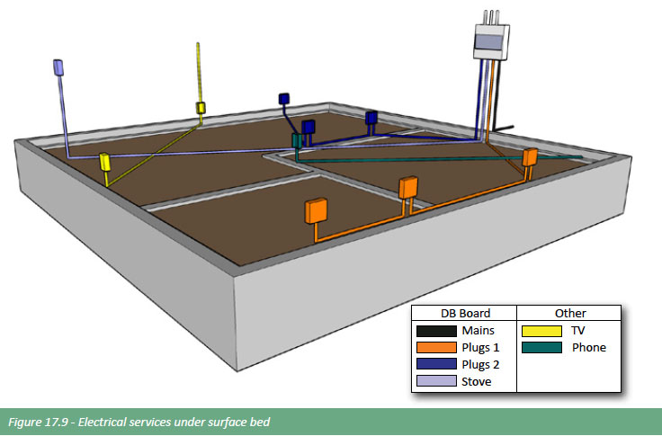
On a residential project it all starts at the boundary where the electrical feed (cable) from the supplier enters a meter box. The meters measure electrical consumption. A cable is then laid from the meter box to the distribution board in the house. From the distribution various circuits are distributed in PVC conduits to all parts of the house. There may be two plugs circuits, two lighting circuits, one for the stove, one for the geyser etc. The distribution box is positioned and the conduits laid first. Plug conduits or usually laid in the concrete surface bed (floor slab) and then rise up to the position of the plug point (socket). Conduits for Lights points and switches are usually laid in the roof and extend down to switching points are wall light points.
Once all the conduits are installed with draw boxes, plug boxes, switch boxes etc, the wires are the drawn through the conduits from the distribution board to the relevant boxes. Normally after the plastering, first coat painting and ceiling are complete wiring is connected to switches and sockets and circuit breakers in the distribution board. There are a number of other components in the distribution board such as an earth leakage. Once the house is nearly complete all switches and cover plates are finally fitted along with light fittings. Testing of the electrical system is done before the final test and issuing of a compliance certificate of compliance is issued. This is a very basic and simple overview of a residential installation. Reading what is contained is this section will help on appreciate what can be included in an electrical installation.
Lighting
Lighting Overview
Lighting is of critical importance in buildings as an adequate level and distribution of light is vital if visual tasks are to be carried out safely and effectively. Good lighting will also improve the internal environment, appearance, and highlight the features of a building. Lighting should be used to supplement daylighting which makes design, planning and functionality of lighting one of the most important elements when building. Lighting also needs to be efficient and cost effective; the use of efficient lamps, ballasts and luminaires, with appropriate lighting controls, can provide the right visual environment, be energy efficient and cost effective, and save on electricity costs.
As with any design related project, the budget is central to the design; this is usually established by applying a certain percentage of the overall building budget towards the “architectural professional”. As a rule of thumb,the suggested budget for lighting is calculated at 4-5 %. Ideally an accurate quotation should be obtained as soon as the lighting layout is available, even if only provisional.
It is possible to save substantial amounts of money by using energy efficient lighting. CFLs and LEDs are available in most lamp base types. LEDs whilst improving technology and efficiency are now better priced and are the best option in terms of saving energy and the planet.
National building regulations states that all:
Lighting installations in new dwellings and buildings, to be served by artificial lighting, should comply with the lighting requirements of SANS 10142: The wiring of premises Part 1: Low- voltage installations. These regulations set out standards of energy efficiency, and provision of lighting controls. The only other standards regulating luminaires are as follows:
- SANS 60570: 2003/IEC 60570: Electrical supply track systems for luminaires
- SANS 60598-2-18: 1993/IEC 60598-2-18 (SABS IEC 60598-2-18), Luminaires: Part 2: Particular requirements – Section 18: Luminaires for swimming pools and similar applications
- SANS 60598-2-23: 2001/IEC 60598-2-23 (SABS IEC 60598- 2-23), Luminaires: Part 2-23: Particular requirements – Extra low voltage lighting systems for filament lamps
Of particular importance is the selection of lamp types which are not discussed in the above standards, however they are covered in the next section.
Lighting design principles
When designing or planning lighting, ensure that light is directed to where it is needed and not ‘wasted’. Take into account the purpose of the space and the tasks to be performed there. Correct positioning and the right fittings and lamps are essential.Artificial lighting can be categorized as:
- General
- Functional or task
- Accent
- Mood or ambience
Except in the case of feature lights, the purpose of a fitting is to provide light – not to make a décor statement. Downlights are unobtrusive and provide excellent light that can be directed where needed and adjusted later if the décor changes. In a home, straight rows and ceiling patterns are less important than lighting up working surfaces in a kitchen or artwork and features.
Downlights (DL) that tilt and rotate allow for greater flexibility but do cost more. Tilt only DL are often the same price as a fixed DL but even if they do cost a little more, it is worth spending the extra. The DL comprises a fitting and a lampholder – the wire connecting the lamp to the power circuit- and a transformer if the system is 12V. NB the lampholder is different for a 12V or 230V system so that decision needs to be made before buying any fittings.
The shape of a DL does not affect the light output. Round, white DL are the most commonly used for practical reasons. Lining up square or triangular DL makes for a time consuming installation, whereas if a round DL is a mm or two out it will not be noticed. Stainless steel, brushed aluminium and other colours also tend to draw the eye up to the ceiling when the focus should be on the home and its contents, and are subject to trends that come and go.
Decorative fittings include chandeliers and wall lights. Consider not only the visual appeal but practical aspects like glare, cleaning – is the fitting an insect trap? Will a wall light interfere with décor and artwork? Will it ‘date’ the home? Check the lampholder – can you use an energy saving lamp?
Centre ceiling lights – hanging or mounted flush with the ceiling were the norm in older homes. If the light output/ number of lamps is sufficient to light the area, they can be cost effective on installation and functional.
A hanging light can cause a shadow on the ceiling above and make a room appear gloomy. A central fixed light can be dimmed (depending on the lamp and switching) but allows less flexibility in terms of ambience than DL.
Factors that influence the number of fittings required include not only the size of the room, but the height of the ceiling, positioning of windows and doors, as well as the colour of the surfaces – floor, walls and ceiling. Dark colours absorb light so more fittings or higher wattage lamps will be needed. Light colours reflect light.
Illuminance Assignments for CBECS Building Activity Categories
Illuminance ranges were adopted from the 1987 Illuminating Engineering Society (IES) Lighting Handbook. The IES lluminance ranges represent the amount of light required for certain activities that take place in various types of buildings.
Illuminance is measured in either lux (lumens per square meter) or footcandles (lumens per square foot). The two measurements differ by a factor of approximately 10 (i.e., 20 lux » 2 footcandles).
Illuminance Degradation
When planning lighting, allowance must be made for the degradation or depreciation of the lamps light output efficiency. Fluorescents in particular can depreciation 10% in 6 months. Modern technology is reducing these losses. Significant depreciation of light output can result in serious non-compliance in terms of lighting level regulations.
Understanding light technologies
In the residential environment, the most commonly used technologies include incandescent, halogen, fluorescent and LED, with limited metal halide application – mainly in spots and security lights.
Incandescent lamps
Incandescent lamps are “standard” electric light bulbs that were introduced for residential use more than 125 years ago by Thomas Edison. They have the lowest initial cost, excellent colour rendering and switch on to full brightness instantly but are expensive to run as they are very inefficient as a light source and have a short life span (1000 hours). Incandescent technology produces light by heating up a metal filament enclosed within the lamp’s glass. More than ninety percent of the energy used by an incandescent light bulb escapes as heat, with less than 10% producing light. Incandescent lamps have largely been replaced with more modern and efficient technologies.
Halogen Lamps
Halogen (tungsten halogen) lamps are a form of incandescent that combines halogen gas with the tungsten filament to produce a chemical reaction (halogen cycle) which redeposits the tungsten back onto the filament thereby increasing the lamps life and keeping the glass clean. Far more efficient than incandescent, halogen lamps became the standard for downlights. They do however operate at a high temperature which be a fire hazard in wooden fittings and installations. Never exceed the wattage recommended for a fitting. Cabinet lights etc designed for installation in bars and kitchens will be safe at the recommended wattage. Heat is generated forward which affects the temperature of the room. They provide good colour rendition. The colour of the light is generally 2700 – 3000K ie warm white .
Compact Fluorescent Lamps (CFL)
Compact fluorescent lamps (CFLs) have been available for residential use for about 30 years, with technological advances improving their quality and popularity. A CFL is a fluorescent tube using gases and phosphor – wound, twisted r folded – with a built in ballast in the base to regulate the current and o is available with an ES (screw) or BC (bayonet) base in all sizes. Non integrated 2 or 4 pin CFLs are used in some fittings and have only the starter built into the lamp. These therefore require a separate ballast. Designed to replace incandescent lamps, CFLs are extremely energy efficient with a 16-18W lamp providing the same amount of light as a 60W incandescent, and 22-24W replacing a 100W lamp. They operate at a low temperature and are available in most lamp bases and ‘colours’ or Kelvin ratings. Dimmable lamps require a compatible dimmer module. CFLs require a warm up period to reach full brightness. Lamplife is shortened by on/off switching.
CFLs contain mercury and must be disposed of safely.
Linear Fluorescent Lamps
Linear fluorescent lamps are the long ‘4 foot and 5 foot’ fluorescent tubes used in garages for decades. They are low pressure mercury vapour gas discharge lamps with a phosphor coating on the inside of the tube. The electric current excites the mercury vapour which produces shortwave ultraviolet light that in turn causes the phosphor coating to glow. The current is regulated with a ballast – magnetic or electronic. The colour rendition in older lamps was extremely poor – around 60 with mainly yellow and blue. This caused problems as red objects would appear brown. Modern lamps with a triphosphor coating now have a CRI (colour rendering index) of around 85.
The tubes used in the home and offices are generally T8. Tubes are measured in 1/8 of an inch. A T8 is therefore 8/8 ie 1 inch in diameter; a T12 is 12/8 or 1.5 inches. T5 are the most super efficient technology and can last up to 20 000 hours. The lamps are shorter than standard T8 lengths and require special fittings. Manufacturers vary but on average the tubes produce 80- 110 lm/W. Linear fluorescent tubes are also used in many decorative fittings, especially for kitchens.
Fluorescent tubes contain mercury and must be disposed of safely.
What is a ballast?
A ballast is a device that serves to control the flow of power to a fluorescent lamp. Advanced electronic ballasts have replaced many magnetic ballasts of the past in new CFL bulbs and fixtures. Electronic ballasts improve fluorescent energy efficiency even further, eliminate the “hum” and visible flickering found in older fluorescent technology, and some are compatible with dimming and daylight controls.
Light Emitting Diodes (LEDs) Light Emitting Diodes (LEDs) are the latest and most efficient technology in lamps. Initially clusters of LEDs were used in lamps but now high power chips are also used. LED chips need controlled direct current (DC) so a circuit is required to convert the alternating electrical supply – the chip and circuitry are critical to the performance of the LED and warrant spending extra for quality. Cheap is not a good option in LEDs.
LEDs are adversely affected by high temperature, so heat sinks and cooling fins are used to draw the heat back and away from the chip. This results in significantly cooler room temperatures as well. LED lamps are available in most lamp base types and are therefore compatible for most fittings as a retrofit. 12V and 230V lamps use different lampholders.
Unlike other lamps where the wattage indicates power consumption and light output, in LEDs the wattage only indicates power consumption. Light output is related to the lumens produced by the chip so all LEDs output are rated in lumens per watt (lm/W), and this can vary from 50 lm/W to 120 lm/W – with performance constantly improving with technological advances. This means that when comparing two 5W LED lamps from different manufacturers, one may be twice as bright as the other.
An LED lamp packaging should show the lumen output, power consumption in watts, colour temperature in kelvins and/or description (e.g. “warm white”), operating temperature range, and sometimes the equivalent wattage of an incandescent lamp.
Other lighting technologies
Induction lighting
An electrodeless lamp or induction light is a light source in which the power required to generate light is transferred from outside the lamp envelope to inside via electromagnetic fields, in contrast with a typical electrical lamp that uses electrical connections through the lamp envelope to transfer power.
There are three advantages of eliminating electrodes:
- Extended lamp life, because the electrodes are usually the limiting factor in lamp life.
- The ability to use light-generating substances of higher efficiency that would react with metal electrodes in normal lamps.
- Improved collection efficiency because the source can be made very small without shortening life, a problem in electroded lamps.
Gas discharge lamps
Gas discharge lamps are not common in the residential environment but may be used outdoors for security lighting. Smaller metal halide fittings have several applications.
Sodium lamps
A sodium-vapour lamp is a gas discharge lamp that uses sodium in an excited state to produce light. Current is regulated with a ballast. Colour rendition is poor – yellow.
Note:Sodium is extremely dangerous and will burst into flames if the lamp is broken.
Lamps must be broken under water to allow for the sodium reaction before being disposed of. Although classified with HID (high intensity discharge) lamps, the sodium lamps are more closely related to fluorescents.
Low Pressure Sodium
Used outdoors due to poor colour rendition – particularly in street lights. The inner discharge U shaped tube is enveloped in a glass vacuum tube for thermal insulation. 5 to 10 minute warmup, but re-strikes are instant. Lumen output does not decrease with age although energy usage may increase up to 10%. The colour rendition is poor – monochromatic yellow light – which inhibits colour vision at night. 1800K Lighting pollution is limited (only emits 2 dominant spectral lines) Very efficient at 200lm/W with a lamp life of 18000 hours.
Do NOT look at LPS lamps for long – it will affect your vision and make you colour blind’ for several hours
High Pressure Sodium
The HPS lamps are smaller and have a broader spectrum of light and better colour rendition (still poor). The current is regulated by an inductive ballast. Produces 80-140lm/W and lamp life is 24000 hours.
Contains mercury and must be disposed of correctly.
Mercury Vapour
A gas discharge lamp, using an electric arc through vapourised mercury. The charge is usually restricted to a small fused quartz arc tube within a larger oval shaped borosilicate glass bulb which provides thermal insulation and protection from the ultraviolet light produced. Current is regulated with a ballast. Used for overhead lighting in large areas, sports arenas and street lights. Startup is 4 – 7 minutes. If the lamp is switched off, no re-strike is possible until the lamp has cooled off (typically 20 minutes). Although the light is white, it has a distinctive blue/green tint which is not flattering to the human skin and these lamps should not be used in a retail environment. Where the outer glass is lined with phosphor, a better colour rendition is achieved. Lamp life 24000 hours Produces 35-65lm/ of high intensity white light. Contains mercury and must be disposed of correctly.
Metal Halide
A high intensity discharge gas discharge lamp, that produces light by an electric arc through a gaseous mixture of metal halides and gaseous mercury. This takes place in the inner tube (fused quartz ie pyrex) which is enclosed within a larger tube, current is regulated with a ballast. High rendition of white light. Lamp life 20000 hours when mounted with base up, or 10000 hours if mounted horizontally. Widely used indoors and out, retail, industrial, sports, parking lots, security lighting – overhead lighting. CRI 65-90. Produces 65-115lm/W.
Contains mercury and must be disposed of correctly.
Lighting controls
Ballasts/control gear
Ballasts are either electromagnetic or electronic; electromagnetic ballasts consist of a wire-wound choke and starter switch; electronic ballasts operate the lamp at high frequency (HF). The electronic (HF) ballasts are more efficient than the electromagnetic ballasts.
The power a lamp consumes (Watts) depends on the type of lamp and also on the ballast or control gear. Fluorescent and discharge lamps require a starter and ballast to control the current through the lamp. The more efficient electronic ballasts operate the lamp at high frequency, reducing lamp power consumption. Typically, the total circuit power of a high frequency circuit is around 25% less than a lamp with an electromagnetic ballast giving a similar light output. High frequency electronic ballasts are also lighter in weight than their electromagnetic equivalents, are silent in operation and automatically switch the lamp off at the end of its life, eliminating flashing. They may, however, have a shorter life themselves.
Modern electronic control gear and controllers enable lighting to be adjusted to suit individual tastes in the various areas of the home. All discharge lamps (see below) need their own control gear and are generally not interchangeable.
- high pressure sodium (SON) lamps
- low pressure sodium (SOX) lamps
- metal halide lamps, and
- mercury vapour lamps
LED’s also require control gear which are available in different sizes which differ in the maximum number of fittings required per unit including different voltage outputs and wattages.
Dimmers
Dimmers allow the intensity of the light output to be changed easily. This is relevant to reducing brightness, changing the ‘mood’ or ambience, and also saving energy. Filament lamps – incandescent and halogen – can be dimmed very easily. For example, a tungsten halogen filament lamp dimmed to half power (50% of the light) will save about 40% of the energy and extend the lamp life up to 20 times.
Not only is the type of dimmer important, but also its capacity. The dimmer will have a clearly defined range related to the wattage of the load ie 6 x 50W halogen lamps = 300W, and would require a 400-600W dimmer.
CFLs use dimmers designed specifically for that technology, LEDs have their own dimmers. Always ensure that the lamps are dimmable (and ballasts/transformers where used) Failure to use the correct dimmer WILL cause problems. Flickering, humming (inferior quality lamps can also be the problem) or simply not working.
Dimmable lamps are available that can be used as a ‘plugin’ without dimmer modules or special wiring. The dimmer module is built into the lamp. These are more expensive but can change a living or bedroom ambience and allow flexibility with a simple lamp. They provide stepped dimming ie 25%, 50% or 75% as a rule.
Switching
- Light switching should be arranged according to the various functions undertaken, e.g. general purpose lighting, background lighting, functional/task lighting, security lighting.
- Switches for individual light fittings can save electricity but will be expensive to install and could be irritating to live with.
- Switches should be conveniently located without a negative impact on the décor.
- Two way switching (or 3+) provides convenience in switching on and off from different locations.
- Dimmer modules are operated with rotary, toggle or bell press switch controls.
- Use automatic controls where appropriate : daylight and motion sensors, and timers for outdoors, entrances and
security lights.
Daylight sensors
Daylight sensors (photocell controls) can be used to automatically switch on lights or lighting circuits as it grows dark. This is excellent for security and access applications allowing one to enter a lit building without leaving the light on all day and wasting electricity and shortening the lamp life of the fitting.Some light fittings have built in photocells which may perhaps save on installation costs but could cost more in that the fitting then has to be replaced should the photocell become faulty.
Motion and Occupancy sensors
Energy saving, intelligent lighting controls, these sensors differ in both function and technology, using both ultrasonic and passive infrared.
Passive infrared (PIR) detect motion based on heat – when a person enters the room – and have segmented lenses and detect motion when a person crosses between two segments or ‘bands’. PIR are termed line of sight sensors.
Ultrasonic sensors use sound as opposed to heat, and emit low intensity inaudible sound waves and detect changes in those waves as caused by someone walking into the room. They are therefore not line of sight dependent but are volumetric – sound waves fill the space in a room – and can be used in any enclosed space regardless of the shape of the room where PIR would fail.
Motion sensors provide energy savings in that the fitting does not have to be burning all day and night to provide light when needed. These are activated by movement within a certain range. They can also assist as a security warning – if the light is on someone or something has to have triggered it. The downside is that unless carefully positioned, branches may cause false alarms.
Occupancy sensors are very effective inside buildings with areas not occupied all the time by switching lights on when people enter a room and switching off when no motion is detected – the time period can be set.
A combination of technologies can provide solutions to most situations.. for example a motion sensor can switch on the lights in a passage to an infrequently occupied warehouse when people enter of leave the passage, whilst occupancy sensors inside the warehouse will switch those lights on and keep them on until the room is again vacant. If motion sensors are used inside the warehouse it is quite possible that the person could move out of line of sight within the warehouse and the lights would switch off.
Timers are another simpler way of controlling the electricity bill and providing light at predetermined times. Always buy good quality sensors that can be adjusted for greater or less sensitivity, and provide an override switch allowing for manual in control of the lighting if required.
Maintenance
All lamps will require changing at some time – in one or 10+ years. Fittings will also require cleaning. In double volume areas, the need for scaffolding to change lamps every year or two has been reduced thanks to LED technology. It is imperative to choose the best lamp for the function and accessibility.
Cleaning can also be key to maintaining the correct light levels – a light fitting filled with bugs will reduce the light output considerably. Others methods such as using mechanisms to lower and raise lights (big chandeliers) are no longer used as frequently. Energy saving considerations With extreme energy savings required in South Africa. Energy saving lamps should be considered wherever possible, like CFL’s and LEDs.
Refer to Table 17.11.Incandescent lamps
Luminaires (light fittings)
Light output ratio (LOR)
A good guide to luminaire efficiency is the LOR quoted by manufacturers, i.e. the light output of the luminaire divided by the light output of the lamp or lamps inside the luminaire. The LOR is determined by the quality of the materials as well as the basic design of the light fitting. For example, in an opal diffuser luminaire (typical bathroom ceiling light fitting) with a light output ratio of 0.5, half the light given out by the lamp(s) is lost inside the luminaire. For greatest efficiency choose a luminaire with a high LOR.
Spacing to height
Manufacturers will also quote a recommended spacing to height ratio for their luminaires (if requested). This is the ratio of the maximum spacing of the luminaires, divided by their height above the working plane. If luminaires are spaced further apart than this, there may be dark areas between luminaires.
Utilisation factor
Utilisation factor of a luminaire is the proportion of the light emitted by the lamps that reaches a particular plane, e.g. the horizontal working plane, either directly or by reflection. It takes into account the properties of the room, its shape and surface reflectance’s, as well as the luminaire characteristics. A high utilisation factor indicates that most of the light reaches the horizontal plane, but may also mean that there is little light reaching the walls or ceiling. This consideration is important for functional or task lighting.
Direct and indirect lighting
Direct lighting supplied by downlighters is complemented by light coloured room surfaces to soften the effect of the direct lighting, and “wall washer” light fittings to brighten up the walls and avoid the effect of bright patches on walls. Indirect lighting can be supplied by uplighters. When using uplighters for general purpose lighting, it is vital to have a high reflectance matt ceiling to reflect most of the light that falls on the ceiling and it is best to have a ceiling height between 2.5 and 3.5m above the floor. Uplighting can also give a dramatic “washed wall” effect when used outdoors.
Luminaire types
The following information is intended to illustrate the types of fittings available and the categories to which they are classed. The product range per category is too vast to cover in this publication. Further detail of product choice, range and specifications is contained in product literature available through manufacturers, distributors and light fitting merchants. A visit to an established light fitting showroom will provide the reader an indication of what products are available per category listed.
Refer to table 17.20 Luminaire types.
Converting to energy saving lighting – LED or CFL
The constant threat of load shedding, increasing electricity costs and reducing prices on LED lamps are making the conversion to energy efficient lighting a serious consideration. This can be done in stages – even one room at a time – to accommodate budget constraints.
- Changing a 100W incandescent lamp to a 23W CFL is a 75% saving
- Changing a 50W halogen lamp to a 5-7W is an 86-90% saving
- Remember to check the lumen output for the replacement lamps
- Also check the lamps kelvin rating and beam angle.
What to convert?
Bulkheads, ceiling lights, wall lights, chandeliers – check the lamp-holder. LED and CFL lamps are available for most lamp base types :
Bulkheads, ceiling lights, wall lights, chandeliers – check the lamp-holder. LED and CFL lamps are available for most lamp base types :
- ES – 14mm and 27mm screw type
- BC – 15mm and 22mm bayonet
- Bipin (capsule) lamps GU5.3
It is also usually relatively easy to change the lamp-holder in a favourite light fitting.
Downlights:
First determine whether your existing installation is 230V or 12V.
230V installation
This is a simple lamp swap – the wiring is correct, the lamp holder will be a GU10 Check the Kelvin, the lumen/watt output, the CRI of the lamps, and swap.
NB if you plan on dimming, buy dimmable LED lamps and compatible dimmers
Before discussing 12V conversions, a note on transformers. The power rating is expressed in Watts (W) or Volt-Amps (VA).
Both refer to the power drawn, Watts being the ‘real power’ and Volt-Amps referring to ‘apparent power’
Typically a transformer will be rated in VA for example 50VA or 250VA
An older installation may have one transformer linked to several DL for example 5 x 50W halogen DL connected to a 250VA transformer, or 5 x 50W halogen DL connected to individual 50VA transformers.
If your installation is 12V and you want to swap to 230V LED lamps
The wiring from the DB to the transformer should meet requirements, but one will need to remove the transformer and connect a GU10 lampholder (correctly earthed) to the 230V power supply with a block connector.
The same DL can be used – only the lampholder changes – and 230V LED lamps can be used as for a new installation.
One of the main advantages of a 12V system in these times of load shedding is that a 12V system uses less wattage so your battery inverter system will run longer.
(volts x amps = watts, so a 12V system can carry more load or require fewer batteries))
To convert the existing halogen 12V system to LED 12V, the following must be considered:
The type of transformer – wire wound electromagnetic (heavy and bulky) electronic.
Whilst an LED may work on the older wire wound transformer, there could be problems. A transformer designed for a 50W load is not ideal for a 6W lamp.
Although an electronic transformer uses modern technology, it may not work at all or will flash on and off because the transformer has a minimum load as well as a maximum and open circuit protection will not recognize a load if too low. Depending on the transformer specs it may be possible to use the transformer connected to several DL to increase the load ie 6 x 6W lamps on a 50VA transformer.
Ideally, one should buy the correct transformer specified for
LED lamps
Dimming – halogen technology uses Leading Edge dimmer modules whilst LED uses Trailing Edge dimmer modules. NB check the load specifications as well.
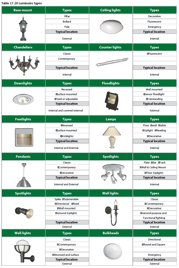
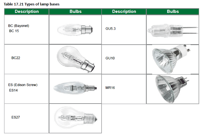
Lighting tips
Internal lighting/luminaire tips
- Luminaires using Halogen lamps offer the best color rendering
- With multiple light sources you can create pools of light and give structure to a room.
- Indirect lighting adds height to a room.
- Create different moods with different light sources. Recessed furniture light turns shelving and cabinets into real eye-catchers.
- Avoid beam angles that are excessively narrow so people around the table are not in shadow. (desk, dining etc.).
- Luminaires integrated in furniture provide light precisely where it is needed.
- You can create different lighting moods with dimmable luminaires.
- Indirect light creates a pleasant glare-free atmosphere.
- Provide adequate lighting over work surfaces and ensure the luminaires are positioned correctly to avoid working in your own shadow.
- Lamps positioned to the left and right of a mirror prevents annoying shadows falling on your face.
- Luminaires using CFLs are not generally recommended in locations where lighting is operated for very short periods with frequent switching (e.g. Guest WC or storerooms) since they take a couple of minutes to warm up and reach full light output, by which time the light is often no longer required.
External lighting/luminaire tips
For smaller type light fittings, try to use luminaires that take a CFL lamp in order to save energy. Where more powerful outdoor lighting is needed, tungsten halogen lamps are commonly used. They are relatively cheap to buy, but have high running costs.
There are four alternatives that have longer lamp lives (typically 14 000–20 000 hours) than tungsten halogen and much lower running costs:
- high pressure sodium (SON) lamps
- low pressure sodium (SOX) lamps
- metal halide lamps, and
- mercury vapour lamps
SON, SOX, metal halide and mercury lamps are more efficient alternatives to the tungsten halogen lamp. The fittings can be relatively expensive but result in much lower running costs, especially for the more powerful lamps. The savings in electricity should pay for the light fittings in 3 years or less, and there will also be longer intervals between re-lamping than for tungsten lamps. All external light fittings should be enclosed to stop moths flying into the bare lamps, causing cool spots and premature lamp failure.
Some useful garden lighting techniques
- Up-lighting a flood light is placed at the base of a tree and angled to light into the branches or onto a particular feature. Cross lighting uses two or more lights to uplight from different angles.
- Down-lighting, also called moon lighting this technique splashes light on to plants and other landscape elements. You can mount the lights in trees or on lamp posts.
- Back-lighting lights the object from behind to cast shadows and create accents. Lighting a wall or fence will silhouette plants in the foreground.
- Path-lighting: these are mainly for safety, lighting up pathways and stairs.
- Highlighting one or more lights are focused on a specific element such as a water feature or plant.
- Use colour filters for interesting effects.
References
Alexander G D & Alexander G C. 2010. Buildaid Building and Pricing Guide 2010/11. Johannesburg: Buildaid Publishing.
Alexander G D & Van As F. 2008: Civil Technology. Johannesburg: EWA Publishing
Radiant Lighting – www.radiant.co.za
Alexander G D & Van As F. 2008: Civil Technology. Johannesburg: EWA Publishing
Radiant Lighting – www.radiant.co.za